Function, Wiring, Disposal – TREND DPIA User Manual
Page 2: Mounting, Dimensions, Dpia data sheet, Trend control systems limited, Trend control systems usa, Weee directive, Fig. 1. wiring details
DPIA
Data Sheet
Please send any comments about this or any other Trend technical publication to [email protected]
rved. Manufactured for and on behalf of the Environmental and Combustion Controls Division of
itzerland by its Authorized Representative.
cation from time to time and make changes to the content hereof without obligation to notify any
(0)1403 211888 Fax:+44 (0)1403 241608 www.trendcontrols.com
el: (425)897-3900, Fax: (425)869-8445 www.trendcontrols.com
DPIA Data Sheet TA200879 Issue 2, 3/03/2009
© 2009 Honeywell Technologies Sàrl, ECC Division. All rights rese
Honeywell Technologies Sàrl, Z.A. La Pièce, 16, 1180 Rolle, Sw
Trend Control Systems Limited reserves the right to revise this publi
person of such revisions or changes.
Trend Control Systems Limited
P.O. Box 34, Horsham, West Sussex, RH12 2YF, UK. Tel:+44
Trend Control Systems USA
6670 185th Avenue NE, Redmond, Washington 98052, USA. T
2
EN0B-0467GE51 R0707
FUNCTION
The DPIA Two-Wire Differential Pressure Transmitters are
equipped with an integrated piezo-resistive pressure
transducer designed so that the pressure to be measured is
applied to a thin membrane made of monosilicon, thus
deflecting it. The semiconductor resistors on the membrane
detect this mechanical deflection and generate an electrical
output signal. The arrangement of the resistors
simultaneously compensates for the temperature response.
The signal of the pressure transducer is converted into the
output signal by high-gain operation amplifiers.
The electrical output signal changes within the specified error
limits in proportion to the applied pressure.
NOTE: All DPIA Two-Wire Differential Pressure
Transmitters are factory pre-set to a response time
of 1s (slow).
NOTE: All DPIA Two-Wire Differential Pressure
Transmitters are factory pre-set to the lower
pressure range 1.
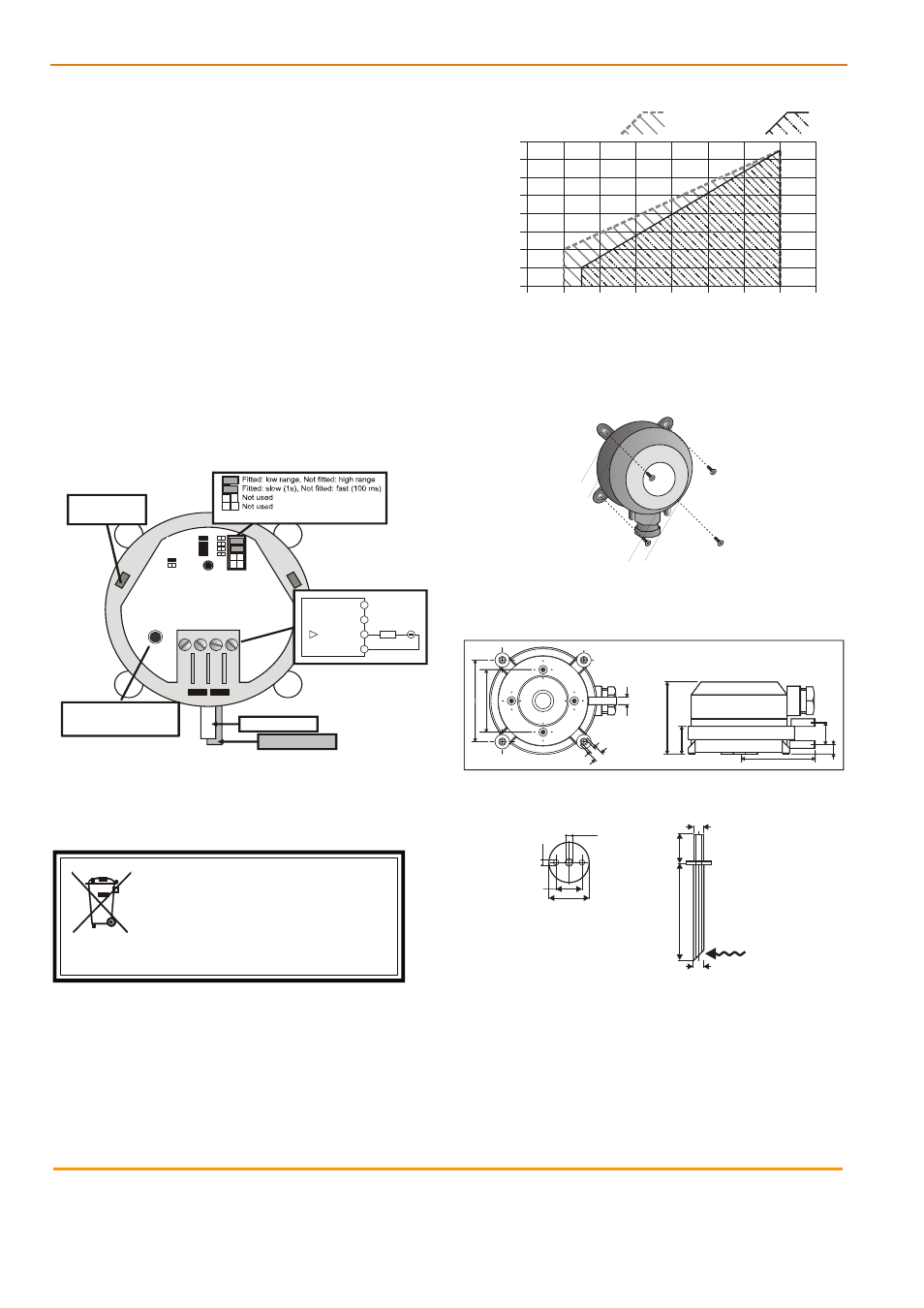
WIRING
Range
low
slow
fast
Response
Input
24 V
D
C
Ou
tp
u
t
4...
20
m
A
D
o
not
us
e
storage positions
for pin plugs
high
P2 (low pressure)
P1 (high pressure)
Differential Pressure Transmitter
DPIA-100-250
Pressure range 0 ... 100 Pa / 0 ... 250 Pa
Overload capacity 25 kPa
Linearity and hyst. Error <= +-1 % FS
Input 15 ... 30 V DC
Output 4 ... 20 mA
3
2
1
load
15 to 30 Vdc
4...20 mA
4 (Do not use)
(Do not use)
D
o
not
us
e
Default: links fitted
Jumper yes
Jumper no
Zero Point Deviation:
Disconnect hoses and press
for 5 s to correct zero offset
1 2 3 4
Fig. 1. Wiring details
DISPOSAL
WEEE Directive:
At the end of their useful life the packa
and product should be disposed of by a
recycling centre.
Do not dispose of with normal household waste.
Do not burn.
permissible Vdc load
permissible Vac load
800
ging
suitable
32
30
28
26
24
22
20
18
16
0
200
400
600
re
sisti
ve loa
d (ohms
)
supply voltage (2-wire versions: Vdc, only)
Fig. 2. Permissible load vs. supply voltage
MOUNTING
Fig. 3. Mounting
It is sufficient to use two screws to mount the unit.
DIMENSIONS
Ш6 (0.24”)
Ш4.5 (0.18”)
8.5 (0.33”)
59 (2.33”)
65.05
(2.56
”)
50
(1.97”)
57.5
(2.26”)
18
(0.70”)
7.5
(0.29”)
22
(0.86”)
Fig. 4. Dimensions in mm (inches)
6.5
4 mm, (0.16”)
60
mm
(2.36”)
18
mm
(0.73”)
Ø6 mm, (0.24”)
3.4
mm
(0.13”)
Ø6.5 mm, (0.26”)
16 mm, (0.63”)
25 mm, (0.98”)
Fig. 5 Connection tube