Ws/r installation instructions, Disposal, Trend control systems limited – TREND WS_R User Manual
Page 2: Trend control systems usa, Weee directive
2
WS/R Rain Detector Installation Instructions TG102665 Issue 2/D 13/03/07
WS/R
Installation Instructions
Manufactured for and on behalf of the Environmental and Combustion Controls Division of Honeywell Technologies Sàrl, Ecublens, Route
du Bois 37,Switzerland by its Authorized Representative.
Trend Control Systems Limited reserves the right to revise this publication from time to time and make changes to the content
hereof without obligation to notify any person of such revisions or changes.
Trend Control Systems Limited
P.O. Box 34, Horsham, West Sussex, RH12 2YF, UK. Tel:+44 (0)1403 211888 Fax:+44 (0)1403 241608 www.trend-controls.com
Trend Control Systems USA
6670 185th Avenue NE, Redmond, Washington 98052, USA. Tel: (425)897-3900, Fax: (425)869-8445 www.trend-controls.com
WEEE Directive :
At the end of their useful life the packaging and
product should be disposed of by a suitable
recycling centre.
Do not dispose of with normal household waste.
Do not burn.
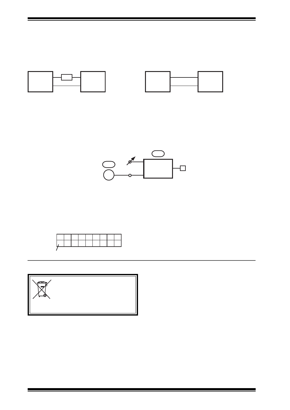
(5)
Using a Trend configuration program configure
the controller to contain the strategy shown
below:
Sensor output:
0 V no rain
1 V rain present
IQ Scaling
It is recommended to use SET (Software Tool) for the setting of sensor type modules. For all IQ2 series controllers with firmware
of version 2.1 or greater, or IQ3 series controllers the following SET Unique Sensor Reference should be used:
Rain Detector V
Alternatively select sensor type module scaling mode 5, (characterise) and enter scaling manually as defined in the table below.
For all other IQ controllers see the Sensor Scaling Reference Card, TB100521A.
S
X
E
F
F
C O M P
K
D
X + 1
V = 5 0
0 = No rain detected
1 = Rain detected
DISPOSAL
Y
E
U
L
P
I
1
I
2
O
1
O
2
0
4
0
0
0
1
1
-
2
0
0
1
0
0
0
0
1
volts, V
Connect the sensor’s heater supply.
(4)
Connect the sensor to the IQ controller’s 24 V
auxiliary supply, or an external 12 V power
supply using the black and white leads as shown
below.
WS/R powered from IQ controller
WS/R powered from external 12 V supply
IQ Controller
auxiliary supply
12 V External
supply
WS/R
WS/R
Black
White
100R
24 Vdc
0 V
Black
White
12 V
0 V
5W
When powering the sensor’s heater from an IQ controller’s 24 V auxiliary supply it is necessary to connect a 100
Ω, 5 Ω resistor
in series with the sensor.
Note that if both the sensor’s power, and heater supply are from an IQ controller’s 24 V auxiliary supply, ensure that enough current
is available (125 mA approx.).
It is now necessary to configure the IQ controller to decode the signal from the sensor.