Llo installation instructions, Installation – TREND LLO User Manual
Page 2
LLO
Installation Instructions
LLO Installation Instructions TG100153A Issue 3/B 10/04/06
2
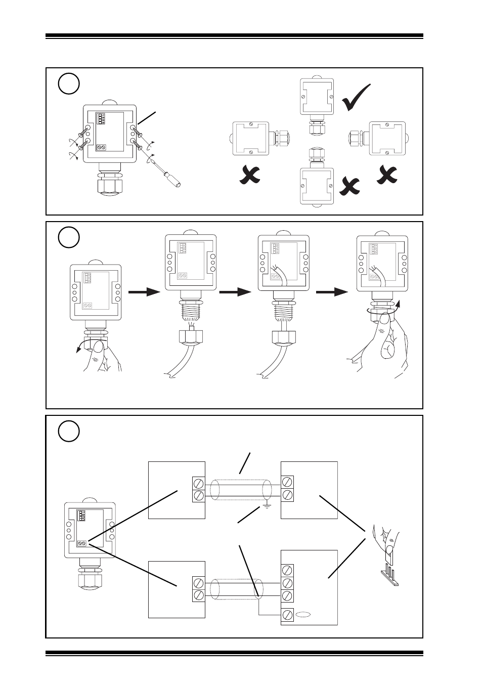
Mount on Wall
4
Insert Cable
5
Wire to Controller
6
Installation
(continued)
4 off Ø 3.5 mm
fix using 2
screws
minimum
Note that IP65 rating is only achieved if the sensor is correctly installed with cable gland fully
tightened.
- +
IQ1 or IQ2
24 Vdc
IN
+
-
Terminate screen at
IQ end only
Sensor, although
marked, is polarity
independent
Sensor
IQ3
0 (0 V)
N (in)
+
-
Sensor
+ (24 V)
Analogue input
channel linked
for current (I)
I
Cable 1.5 mm
2
cross-sectional area (16 AWG) maximum
See also other documents in the category TREND Hardware:
- PN-VPC (2 pages)
- DPCM (24 Vac_dc) (4 pages)
- 2VID (24 Vac_dc) (4 pages)
- 6RM_24VAC (4 pages)
- 3RM_24VAC (4 pages)
- 2RM_24VAC (4 pages)
- 2SRM (24 Vac_dc) (4 pages)
- SRMAC (4 pages)
- 4DiX_24Vac (4 pages)
- AD20-xx (4 pages)
- AD05-xx (4 pages)
- AL0406-P-SU (2 pages)
- AL0206-P-K (2 pages)
- ACCA_VB_ADK (1 page)
- AT0102-24 (2 pages)
- V162X (4 pages)
- V584 (2 pages)
- V583 (2 pages)
- NXIP (8 pages)
- NXNI (8 pages)
- NX Variable Speed Drives (136 pages)
- NXL Variable Speed Drives (12 pages)
- XW_R_IQ (4 pages)
- ACCW_RW_IQ (4 pages)
- TW_S (4 pages)
- TW_P (4 pages)
- PCW_... (4 pages)
- OCC_U (4 pages)
- LLS (4 pages)
- WS_R (2 pages)
- WS_S, _SD (4 pages)
- AQ_S (4 pages)
- AQ_D (4 pages)
- DPSL (4 pages)
- DPSA (4 pages)
- PIl3 (4 pages)
- DPIL (4 pages)
- DPIA (2 pages)
- HT_O (8 pages)
- HT_D (4 pages)
- HT_S (4 pages)
- T_FS (4 pages)
- T_FG (4 pages)
- T_AV (4 pages)