Installation instructions pcw/... installation – TREND PCW_... User Manual
Page 3
PCW/... Wireless Pulse Counters Installation Instructions TG200834 Issue 1/B 21/09/05
3
Installation Instructions
PCW/...
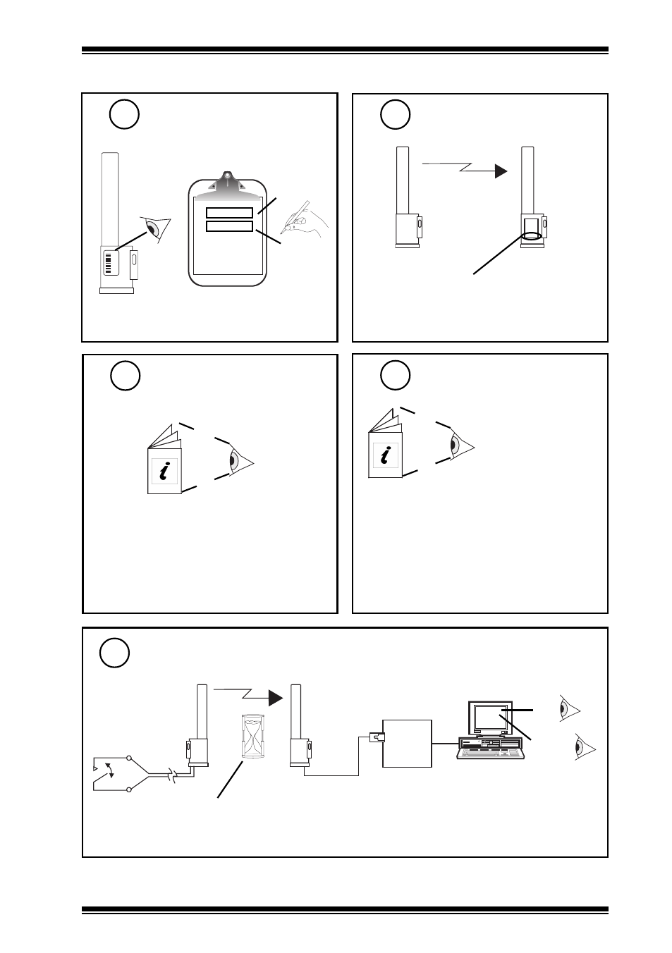
INSTALLATION
(continued)
XW/R/IQ Installation Instructions TG200783
Note Identification Number
5
000016746
00016746
‘number’
‘location’
Install and Configure
XW/R/IQ Receiver
7
Configure IQ
8
TW/.., PCW/..,
XW/R/IQ Data Sheet
TA200780
For IQ3 the sensor’s target analogue node must
be created using SET. An example strategy
including decoding of alarm bits is given in the
TW/.., PCW/.., XW/R/IQ Data Sheet.
Alarm Bits:
Bit 3: loss of reception (from XW/R/IQ)
Bit 1: low battery (from sensor)
Bit 0: input state (from PCW/STATUS only)
Test System
9
IQ
Δ V
XW/R/IQ
PCW/...
PCW/METER: 1 min.
PCW/STATUS: 4 min (and change of state)
Note that the PCW/... initial value should be recorded
as it will vary from unit to unit. The pulse counter
has been designed not to have reset capability in
order to prevent fraud.
Check Receiver Serial
Number
6
XW/R/IQ
PCW/...
For PCW/METER, XW/R/IQ serial number
is 2407401 or greater.
For PCW/STATUS, XW/R/IQ serial number
is 250517 or greater.
X
W
/R
/IQ
2 4 0 7 4 0 1
Δ Status
Bit 3: loss of reception
Bit 1: low battery
Bit 0: input state
PCW/STATUS only