Nxl data sheet, Specifications, Trend control systems limited – TREND NXL Variable Speed Drives User Manual
Page 12: Trend control systems usa, Electrical, Environmental, 10 °c (no frost) to +40 °c: (i
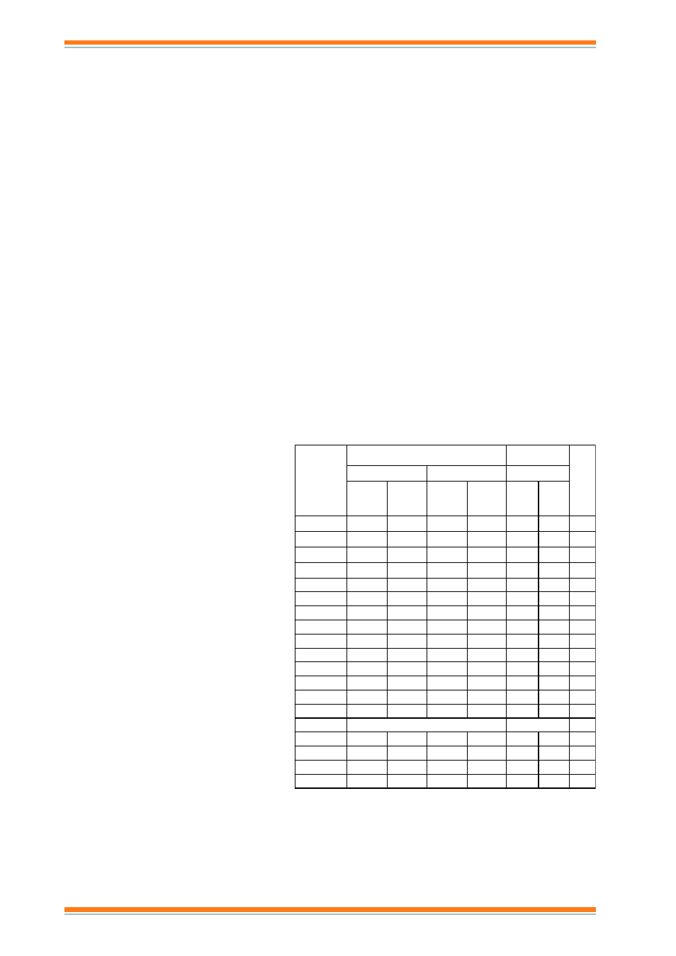
NXL
Data Sheet
12
NXL Variable Speed Drives Data Sheet TA200620 Issue 1/G 13/06/07
Manufactured for and on behalf of the Environmental and Combustion Controls Division of Honeywell Technologies Sàrl, Ecublens, Route
du Bois 37,Switzerland by its Authorized Representative, Trend Control Systems Limited.
Trend Control Systems Limited reserves the right to revise this publication from time to time and make changes to the content
hereof without obligation to notify any person of such revisions or changes.
Trend Control Systems Limited
P.O. Box 34, Horsham, West Sussex, RH12 2YF, UK. Tel:+44 (0)1403 211888 Fax:+44 (0)1403 241608 www.trend-controls.com
Trend Control Systems USA
6670 185th Avenue NE, Redmond, Washington 98052, USA. Tel: (425)897-3900, Fax: (425)869-8445 www.trend-controls.com
r
e
d
r
O
e
d
o
C
y
t
il
i
b
a
d
a
o
L
r
e
w
o
P
t
f
a
h
S
r
o
t
o
M
)
W
k
(
P
t
h
g
i
e
W
)
g
k
(
w
o
L
h
g
i
H
c
a
V
0
8
3
d
e
t
a
R
s
u
o
u
n
i
t
n
o
C
I
t
n
e
r
r
u
C
L
)
A
(
%
0
1
d
a
o
l
r
e
v
o
t
n
e
r
r
u
c
)
A
(
d
e
t
a
R
s
u
o
u
n
i
t
n
o
C
I
t
n
e
r
r
u
C
H
)
A
(
%
0
5
d
a
o
l
r
e
v
O
I
t
n
e
r
r
u
C
S
)
A
(
w
o
L
C
g
e
d
0
4
)
W
k
(
P
h
g
i
H
C
g
e
d
0
5
)
W
k
(
P
5
1
0
0
0
L
X
N
9
.
1
1
.
2
3
.
1
2
5
5
.
0
7
3
.
0
0
.
1
5
2
0
0
0
L
X
N
4
.
2
6
.
2
9
.
1
9
.
2
5
7
.
0
5
5
.
0
0
.
1
5
C
/
2
C
3
0
A
A
L
X
N
3
.
3
6
.
3
2
.
2
3
.
3
1
.
1
5
7
.
0
5
5
C
/
2
C
4
0
A
A
X
N
3
.
4
7
.
4
3
.
3
5
5
.
1
1
.
1
5
5
C
/
2
C
5
0
A
A
L
X
N
6
.
5
9
.
5
3
.
4
5
.
6
2
.
2
5
.
1
5
5
C
/
2
C
7
0
A
A
L
X
N
6
.
7
4
.
8
6
.
5
4
.
8
0
.
3
2
.
2
5
5
C
/
2
C
9
0
A
A
L
X
N
9
9
.
9
6
.
7
4
.
1
1
0
.
4
0
.
3
5
5
C
/
2
C
2
1
A
A
L
X
N
2
1
2
.
3
1
9
5
.
3
1
5
.
5
0
.
4
5
5
C
/
2
C
6
1
A
A
L
X
N
6
1
6
.
7
1
2
1
8
1
5
.
7
5
.
5
1
.
8
5
C
/
2
C
3
2
A
A
L
X
N
3
2
3
.
5
2
6
1
4
2
1
1
5
.
7
1
.
8
5
C
/
2
C
1
3
A
A
L
X
N
1
3
4
3
3
2
5
3
5
1
1
1
1
.
8
5
C
/
2
C
8
3
A
A
L
X
N
8
3
2
4
1
3
7
4
5
.
8
1
5
1
5
.
8
1
5
C
/
2
C
5
4
A
A
L
X
N
6
4
1
5
8
3
7
5
2
2
5
.
8
1
5
.
8
1
5
C
/
2
C
1
6
A
A
L
X
N
1
6
7
6
6
4
9
6
0
3
2
2
5
.
8
1
c
a
V
0
4
2
o
t
8
0
2
1
C
2
0
0
0
L
X
N
4
.
2
6
.
2
7
.
1
6
.
2
7
3
.
0
5
2
.
0
0
.
1
1
C
3
0
0
0
L
X
N
7
.
3
1
.
4
8
.
2
2
.
4
5
7
.
0
5
5
.
0
9
.
1
1
C
4
0
0
0
L
X
N
8
.
4
3
.
5
7
.
3
6
.
5
1
.
1
5
7
.
0
9
.
1
1
C
6
0
0
0
L
X
N
6
.
6
3
.
7
8
.
4
2
.
7
5
.
1
2
,
1
0
.
2
SPECIFICATIONS
Electrical
Supply voltage
Three phase units :380 to 500 Vac -15% +10% 3 phase, 45
to 66 Hz
Single phase units :208 to 240 Vac -15% +10% 1 phase, 45
to 66 Hz
Motor voltage
:0 to supply voltage
Motor current
Rated output
:I
L
, 1.9 A to 61 A dependent on option
(continuous current under low overload,
10% for 1 minute every 10 minutes, 150%
starting torque requirement, 40 °C
ambient temperature e.g. fans, pumps)
High overload
:I
H
, see table (continuous current under
high overload, 50% for 1 minute every
10 minutes, 200% starting torque
requirement, 50 °C ambient temperature
e.g. cranes, hoists, lifts)
Starting Current
:2xI
H
, (maximum current required for 2 secs
every 20 secs if output frequency <30 Hz,
and heat sink temperature <+60 °C )
Output frequency
:0 to 320 Hz
Frequency resolution :0.01 Hz
Control method
:Frequency control, Open loop
sensorless vector control
Switching frequency
:1 to 16 kHz (factory default 6 kHz)
Frequency reference
Analogue input
:Resolution 0.1% (10 bit), accuracy ±1%
Keypad reference :Resolution 0.01 Hz
Field weakening point :30 to 320 Hz
Acceleration time
:0.1 to 3000 secs
Deceleration time
:0.1 to 3000 secs
Braking torque
Environmental
Operating Temperature:-10 °C (no frost) to +50 °C: (I
H
)
-10 °C (no frost) to +40 °C: (I
L
)
Storage temperature
:-40 °C to +70 °C
Relative
humidity
:0 to 95 %RH non-condensing,
non-corrosive, no dripping water
Air quality
chemical vapours :IEC721-3-3, unit in operation class 3C2
mechanical particles
:IEC721-3-3, unit in operation
class 3S2
Altitude
100% load capacity (no derating) up to
1000 m. 1% derating for each 100 m
above 1000 m (max. 3000 m)
Vibration
:EN50178 and EN60068-2-6
Shock
:EN50178 IEC 68-2-27. UPS drop test
(for applicable UPS weights)
Enclosure class
:IP20, IP21, IP54 (see codes p9)
EMC Immunity
:EN50082-1, -2, EN61800-3
EMC Emissions
MF2, MF3
:EMC level N. Can have external filter to
achieve level H.
MF4 to MF6
:EMC level H:EN61800-3(1996) + A11
(2000) (1st environment, restricted use,
2nd environment), EN61000-4.
Safety
:Fulfils EN50178, EN60204-1, CE, UL,
cUL, FI, GOST R , IEC 61800-5 (check
nameplate for details)
DC brake
:30% T
N
(nominal torque)
without brake option
Protective Functions
Overcurrent
:Trip limit 4.0 x I
H
instantaneously
Overvoltage protection :911 Vdc
Undervoltage protection:333 Vdc
Earth fault protection
:In case of earth fault in motor or
motor cable, only the frequency
converter is protected
Other
:Unit overtemperature
protection, motor overload
protection, motor stall
protection, motor underload
protection, short circuit
protection of +24 V and +10 V
reference voltages
Inputs and Outputs
Analogue voltage input :0 to +10 V, R
in
= 200 k
Ω, single
ended. Resolution 12 bit,
accuracy ±1%
Analogue current input :0 (4) to 20 mA, R
in
= 250
Ω,
differential
Digital inputs
:3 off (Ecodrives have 6).
Positive or negative logic, 18 to
24 Vdc
Auxiliary voltage out
:+24 V ±15 %, 100 mA max.
Reference voltage out :+10 V, +3% 10 mA max.
Analogue output
:1 off. 0(4) to 20 mA, R
L
<500
Ω,
resolution 16 bit, accuracy
±1 %
Digital Output (relay)
:1 off (Ecodrives have 2).
Programmable changeover
relay max. switching capacity:
24 Vdc/8 A, 250 Vac/8 A, 125
Vdc/0.4 A.
Digital Output (open collector) :1 off (Ecodrives only).
50 mA, 48 V