Installation instructions ad05xx, ad10-xx, Wiring – TREND AD10-xx User Manual
Page 3
Installation Instructions
AD05xx, AD10-xx
E
wiring 2-position
control
Floating
control Feedback Modulating
control
D
Verkabelung 2-Positionen-Steuerung
3-Pos.-Regelung Rückmeldung
Stetige
Regelung
DK
Ledninger
Tænd / sluk kontakt
Glideregulering Feedback Modulerende
regulering
ES
Cableado
Control de 2 posiciones
Control flotante realimentación
Control
modulante
F
Câblage
Interrupteur 2 positions
Commande flottante rétroaction
Commande
modulante
I
Cablaggio
Controllo di due posizioni
Controllo flottante
feedback
Controllo modulato
N
Ledningsnett To-plas-serings-betjening
Flytende kontroll
Feedback
Modulerende kontroll
NL
Bedrading
Twee positie schakelaar
Zwevende regeling
Feedback
Modulatie-regeling
P
Cablagem
Comando de 2 posições
Controlo flutuante
realimentação
Controlo de modulação
S
Kablage
Till- / Från-kopplare
Flytande reglering Feedback
Modulerande
reglering
FI
Kaapelointi
Päälle- / pois-kytkin
Liukuohjaus Feedback
Modulaatio-ohjaus
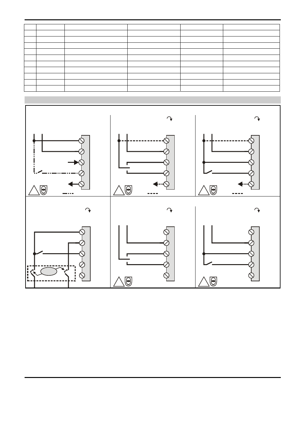
WIRING
C1: AD05-P, AD10-P
!
Modulating: 0[2]...10V, 10...0[2]V
0[2]...10V
0[2]...10V
POS out
POS 50%
Y in
GND/-
24V~/+
24V~/=
3
1
2
5
4
= override option
!
Floating: Dir
0[2]...10V
POS out
= feedback option
CCW
CW
GND/-
24V~/+
24V~/=
3
1
2
5
4
!
2-Position: Dir
0[2]...10V
POS out
CCW
CW
GND/-
24V~/+
24V~/=
3
1
2
5
4
= feedback option
C2: AD05-230, AD10-230
C3: AD05-24, AD10-24
2-Position: Dir
CCW
CW
230V~
3
1
2
5
4
N
L
230V ~
> 3 mm!
!
Floating: Dir
CCW
CW
GND/-
24V~/=
3
1
2
5
4
!
2-Position: Dir
CCW
CW
GND/-
24V~/=
3
1
2
5
4
AD05-xx, AD10-xx Installation Instructions TG200854INT Issue 1/E 14/09/06
3
MU1B-0302GE51 R0806B