Installation instructions 2rm/24vac 3 installation, Wire module to controller, Connect module to hvac equipment – TREND 2RM_24VAC User Manual
Page 3
2RM/24VAC Two Relay Module (24 Vac/dc) Installation Instructions TG200640 Issue 1/C 23/03/07
3
Installation Instructions
2RM/24VAC
3
INSTALLATION
(continued)
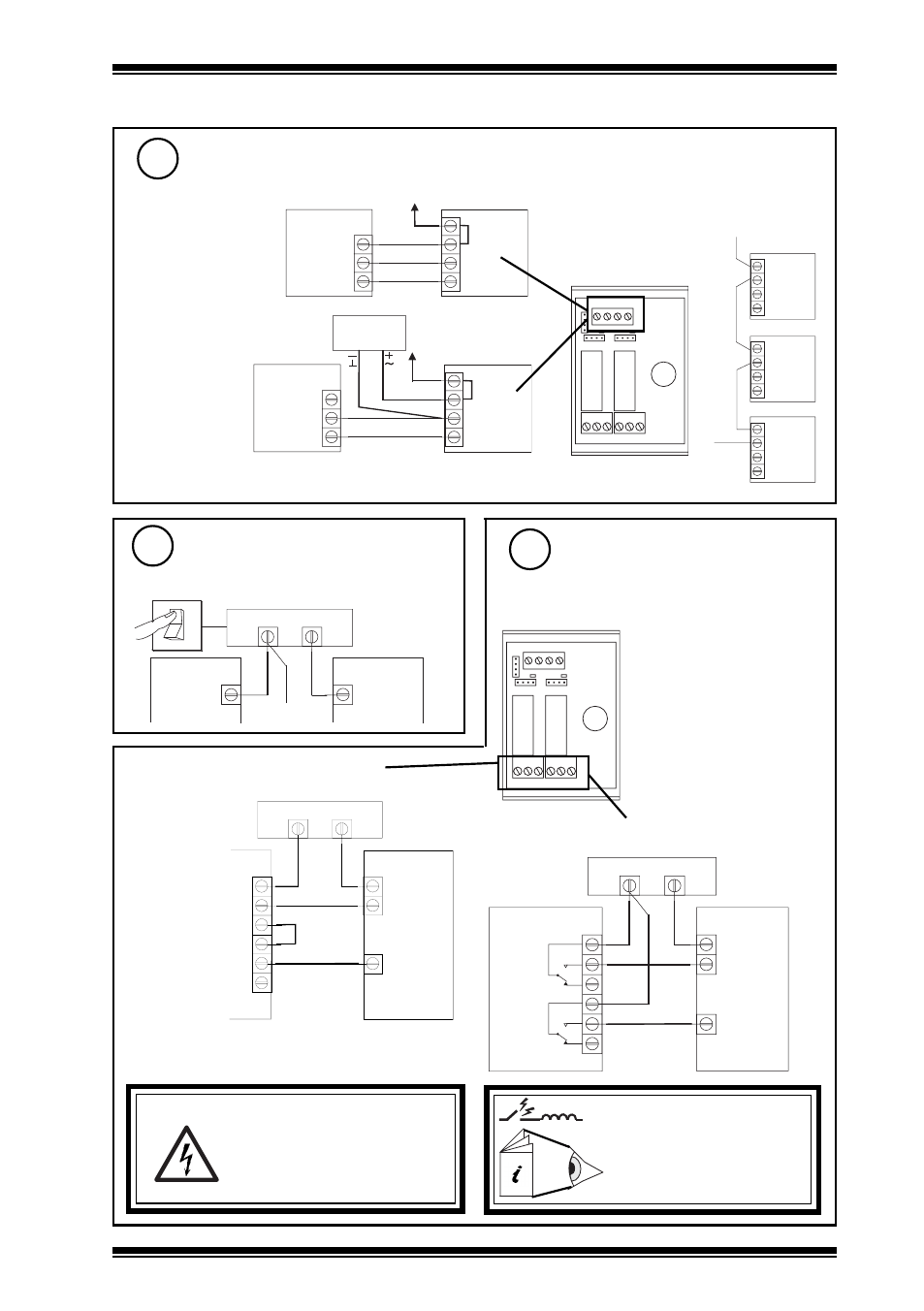
Wire module to controller
8
IN 0V 24V
AUTO ON OFF AUTO ON OFF
HLM RLM
J1
J2
LO
W
/LO
W
E
R
HIGH/RAISE
RL1
RL2
NC NO C
NC NO C
IQ
2RM
24 V
0 V
OUT
0 V
IN
24 V
24 V loop
2RM
XRM
XRM
24 V loop
24 V loop
Ensure Equipment Input
Power Supply is Switched off
9
O
I
2RM
Power Supply
Connect module to HVAC
Equipment
10
IN 0V 24V
AUTO ON OFF AUTO ON OFF
HLM RLM
J1
J2
LO
W
/LO
W
E
R
HIGH/RAISE
RL1
RL2
NC NO C
NC NO C
WARNING:
The wires may be connected
to hazardous voltages.
Disconnect power before
attempting any wiring.
Arc suppression
recommended
Relay Output Arc
Suppression Installation
Instructions TG200208
if HLM (see step 4)
if RLM (see step 4)
Note that this wiring ensures both Raise and
Lower outputs cannot be powered simultaneously.
2RM
High
Low
HIGH/
RAISE
LOW/
LOWER
C
NO
NC
C
NO
NC
Power Supply
2RM
Raise
Lower
HIGH/
RAISE
LOW/
LOWER
C
NO
NC
C
NO
NC
Power Supply
Cable size
0.5 to 2.5 mm
2
(14 to 20 AWG) -
Cu only
Cable size 0.5 to 2.5 mm
2
(14 to 20 AWG) - Cu only
IQ
2RM
24 V
0 V
OUT
0 V
IN
24 V
24 Vac/dc
PSU
or using external
24 Vac/dc supply
either using IQ 24 Vdc
Auxiliary Supply
Note that external 24 V supply should be isolated or earthed (grounded) to IQ earth
(ground); ensure correct polarity
maximum current consumed from supply:
24 Vac 73 mA, 24 Vdc 33 mA
Contacts rated 5 A max. at 240 Vac single
phase only (Cosø>=0.4), and 30 Vdc (resistive
load). 2 A for 24 Vdc (inductive load, T<=30ms).
Equipment
Input power
supply
Equipment
Input power
supply
Equipment
Input power
supply
The UL rating applies to loads
of up to 30 V.