6rm/24vac installation instructions, 3installation, Mount on din rail – TREND 6RM_24VAC User Manual
Page 2: Ab c set auto/on/off links to auto, Wire module to controller, Switch off iq, Continued), 6rm xrm xrm 24 v loop, Cable size 0.5 to 2.5 mm
6RM/24VAC
Installation Instructions
6RM/24VAC Six Relay Module (24 Vac/dc) Installation Instructions TG200649 Issue 1/C 02/04/07
2
O F F
A U T O
O N
A U T O
O N
O F F
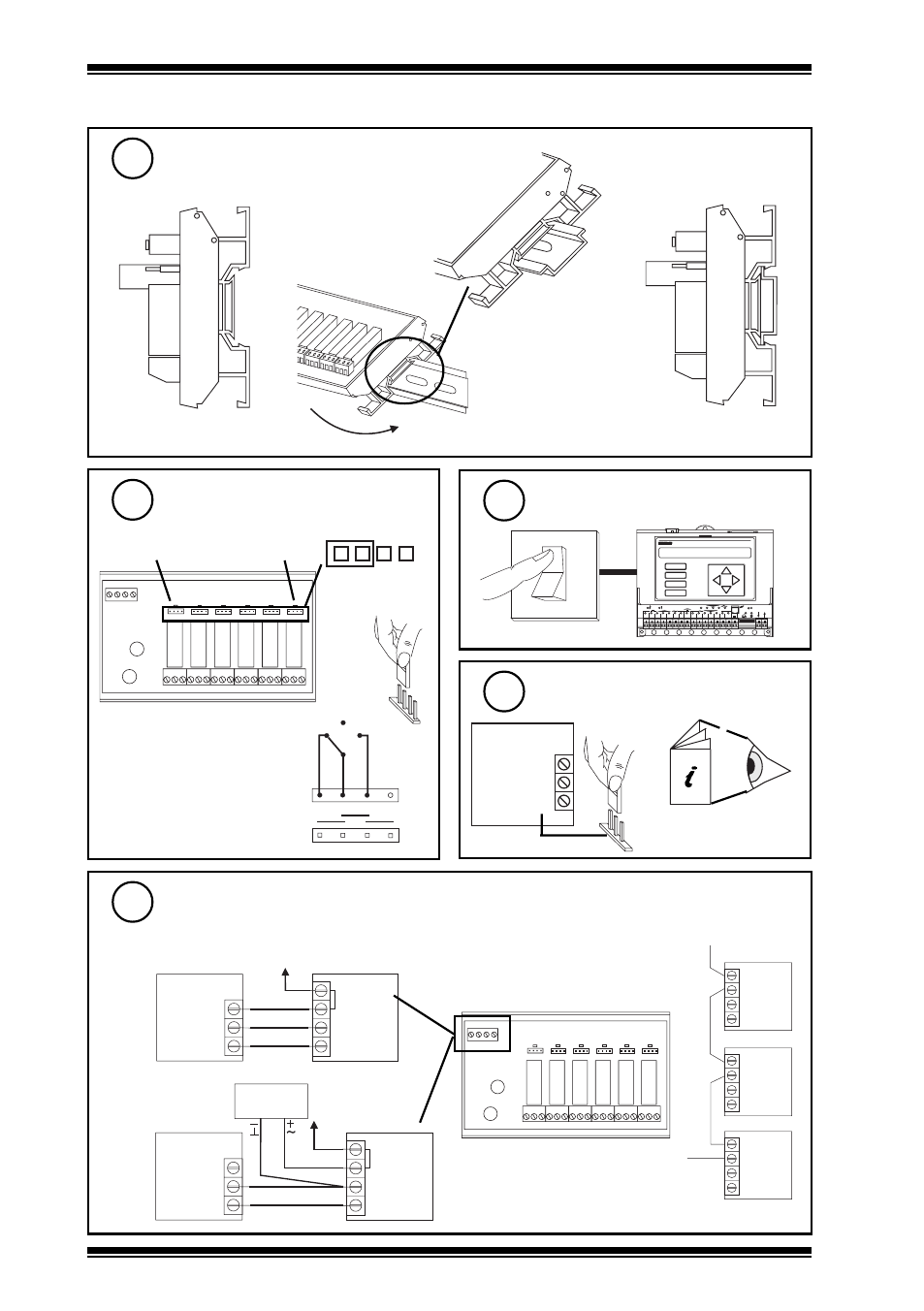
3
INSTALLATION
(continued)
Mount on DIN rail
3
a
b
c
Set AUTO/ON/OFF links to
AUTO
4
IN 0V 24V
AUTO ON OFF
J1
NO
NC
C
NO
NC
C
NO
NC
C
NO
NC
C
NO
NC
C
NO
NC
C
AUTO ON OFF
J2
AUTO ON OFF
J3
AUTO ON OFF
J4
AUTO ON OFF
J5
AUTO ON OFF
J6
A U T O O N
O F F
Note that each link may be
replaced by a three position
(SPDT) switch which will
normally be centre off; this would
be wired as adjacent diagram
(see note step 14).
Wire module to controller
7
IN 0V 24V
AUTO ON OFF
J1
NO
NC
C
NO
NC
C
NO
NC
C
NO
NC
C
NO
NC
C
NO
NC
C
AUTO ON OFF
J2
AUTO ON OFF
J3
AUTO ON OFF
J4
AUTO ON OFF
J5
AUTO ON OFF
J6
6RM
XRM
XRM
24 V loop
Switch off IQ
5
1
2
3
4
5
6
7
8
9
1 0
A
B
C
D
D P
T X
R X
O K
L A N
1
2
3
4
5
6
7
8
9
1 0
1 1
1 2
1 3
1 4
1 5
V
2 4 V
1 6
1 7
1 8
1 9
2 0
O
I
IQ
Ensure IQ Output channel is
Analogue set to Voltage V
6
24 V
0 V
OUT
IQ
IQ Controller
Installation Instructions
V
IQ
6RM
24 V
0 V
OUT
0 V
IN
24 V
24 V loop
24 V loop
IQ
6RM
24 V
0 V
OUT
0 V
IN
24 V
24 Vac/dc
Power Supply
or using external 24 Vac/dc power supply
either using IQ 24 Vdc Auxiliary Supply
link for relay
1
link for relay
6
maximum current consumed from supply:
24 Vac 203 mA, 24 Vdc 86 mA
Note that the external 24 V supply should
be isolated or earthed (grounded) to IQ
earth (ground); ensure correct polarity
Cable size 0.5 to 2.5 mm
2
(14 to
20 AWG), Cu only
24 V