Connect module to hvac equipment, Wire module to controller, Close panel – TREND DPCM (24 Vac_dc) User Manual
Page 3: Switch on iq, Continued), Hvac equipment power supply
DPCM (24Vac/dc) Installation Instructions TG200482 Issue 3 07/07/08
3
Installation Instructions
DPCM (24Vac/dc)
3
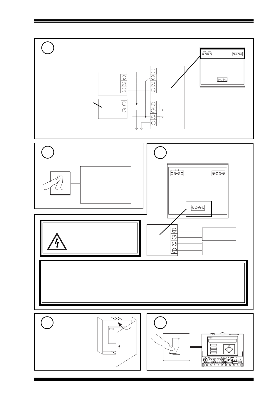
Installation
(continued)
Ensure Power Supply to HVAC
Equipment is Switched off
7
O
I
HVAC Equipment
Power Supply
Connect module to HVAC
equipment
8
OUT2
+
OUT1
IN2
0V 24V
-
+
-
IN1
24Vac
WARNING: The wires may be connected
to hazardous voltages.
Disconnect power before
attempting any wiring.
DPCM
HVAC Equipment
Item 1
OUT 1+
OUT 1-
OUT 2+
OUT 2-
CAUTION
No circuit protection is provided against output short circuits; if this occurs the circuit may be
damaged. The outputs must not be connected or disconnected when the DPCM is powered. The
output circuit must not contain any other switch circuit, such as manual override; if required,
these must be implemented either in the controller strategy, or in the 10 V signal. The outputs
should be connected only to their loads (i.e. kept isolated from earth or other supplies).
Wire module to controller
(continued)
6
OUT2
+
OUT1
IN2
0V 24V
-
+
-
IN1
24Vac
DPCM
IQ
24 Vac
Supply
24V
0V
IN 1
IN 2
0V
OUT 1
OUT 2
24 Vac
ac supply to next module
24 Vac
Using 24 Vac external supply for both control and output supplies
common
Note that external 24 V supply
should be isolated or earthed
(grounded) to IQ earth (ground);
ensure correct polarity
Close panel
9
Switch on IQ
10
OUT2
+
OUT1
IN2
0V 24V
-
+
-
IN1
AC2 AC1
1
2
3
4
5
6
7
8
9
1 0
A
B
C
D
D P
T X
R X
O K
L A N
1
2
3
4
5
6
7
8
9
1 0
1 1
1 2
1 3
1 4
1 5
V
2 4 V
1 6
1 7
1 8
1 9
2 0
O
I
IQ
HVAC Equipment
Item 2