Iq3xact installation instructions, 3 installation - mounting, Connect output power (p) – TREND IQ3xact User Manual
Page 4: Connect auxiliary supply (24 v ), Install auxiliary board
4
IQ3xact Web Enabled Controller Installation Instructions TG200766 Issue 2 21/04/08
IQ3xact
Installation Instructions
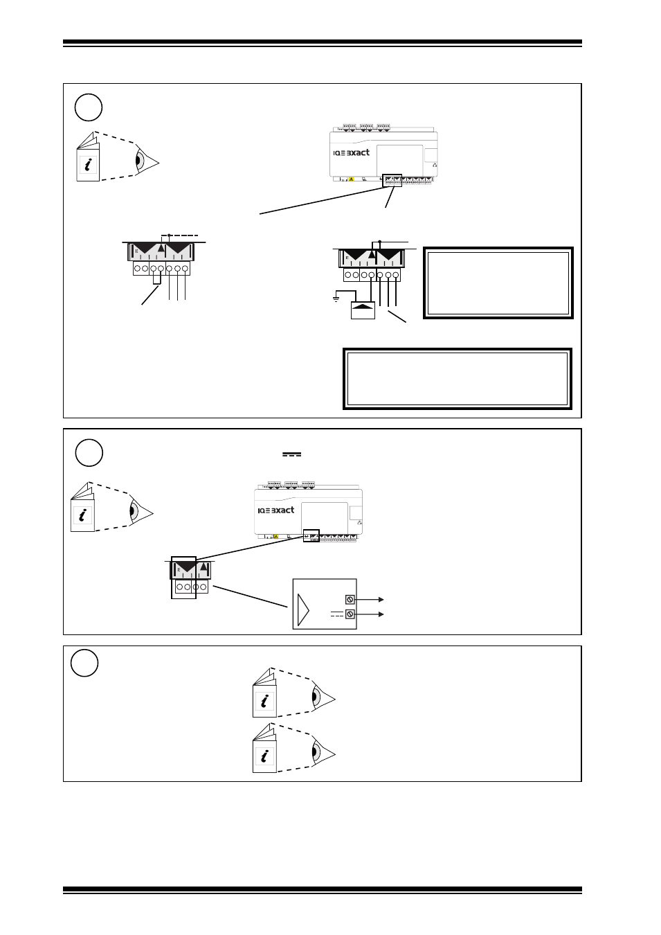
Connect Output Power (P)
9
3 Installation - Mounting
(continued)
either use IQ3 24 Vdc auxiliary supply
4 5 6
2
7 8 9
3
10 11 12
4
13 14 15
5
16 17 18
6
+ 0
+ 0
+ 0
+ 0
+ 0
1 2 3
1
+ 0
0 V
24 V
24 V
34 35 36
12
37 38 39
13
40 41 42
14
A
31 32 33
P
11
43 44 45
15
46 47 48
16
100-240 V
OK RX
P 0 P 0
P 0
P 0 P 0
P 0
A
0 V
24 V
24 V
A
31 32 33
P
11
P 0
A
PSU
0V
24
V
24
V
A
31 32 33
31 32 33
P
11
P 0
or use 24 Vdc or 24 Vac external supply
Fit external link
if P terminal used (see step 8 above)
Check IQ3 24 Vdc combined and
auxiliary output current availability:
IQ3 Configuration Manual TE200768
External PSU
WARNING
External PSU must be dedicated
to I/O channel use, and comply
with relevant EMC and safety
standards
WARNING
If external supply is used, note whether P bus is
24 Vac or 24 Vdc and only connect appropriate output
devices to P output terminals
EN61010:2001 MEASUREMENT
CATEGORY 1
Separate from 230 Vac input power
supply by double or reinforced
insulation
Connect external supply (no external link)
4 5 6
2
7 8 9
3
10 11 12
4
13 14 15
5
16 17 18
6
+ 0
+ 0
+ 0
+ 0
+ 0
1 2 3
1
+ 0
0 V
24 V
24 V
34 35 36
12
37 38 39
13
40 41 42
14
A
31 32 33
P
11
43 44 45
15
46 47 48
16
100-240 V
OK RX
P 0 P 0
P 0
P 0 P 0
P 0
A
0 V
24 V
24 V
A
P
IQ3
24 V
0 V
A
Connect Auxiliary Supply (24 V
)
10
terminal size 0.5 to 2.5 mm
2
(14 to 20 AWG)
Imax = 150 mA(including current to P bus,
- see step 9 above)
if required
Check IQ3 24
Vdc
combined and auxiliary
output current availability:
IQ3 Data Sheet TA200505
Note that the 24 Vdc supply is normally about 22 V
and drops to about 20.7 V at full load.
EN61010:2001 MEASUREMENT CATEGORY 1
Separate from 230 Vac input power supply by double
or reinforced insulation
Install Auxiliary Board
11
IQ3../.../LAN/... Installation Instructions TG200916 section 1
for IQ3../.../LAN/...
IQ3../.../XNC/... Installation Instructions TG200911 section 1
for IQ3../.../XNC/..., including
IQ3../.../LAN/XNC/..., IQ3../.../SER/XNC/...
if fitted (for battery board, XCITE/BBC, see section 4, step 19)
terminal size 0.5 to 2.5 mm
2
(14 to 20 AWG)