Connect inputs (channels 1 to 6), Vi i t d, Segregate screen earth (ground) – TREND IQ3xact User Manual
Page 3: Connect outputs (channels 11 to 16), Continued), 14 to 20 awg) - cu only, 0 (0 v) n (in) + (+24v) n
3
IQ3xact Web Enabled Controller Installation Instructions TG200766 Issue 2 21/04/08
Installation Instructions
IQ3xact
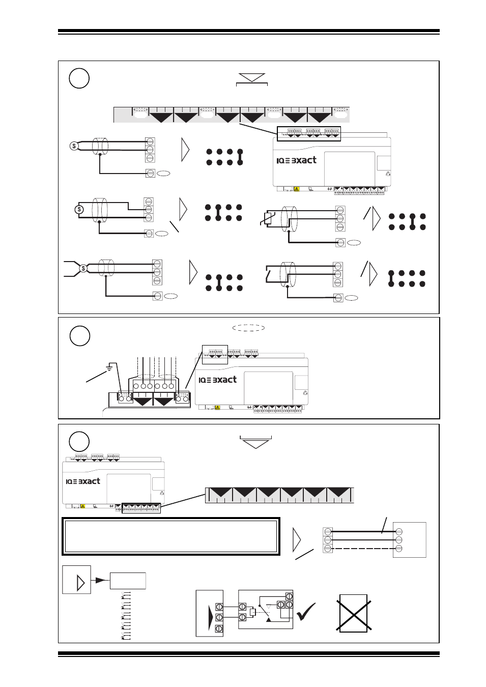
3 Installation - Mounting
(continued)
Connect Inputs (channels 1 to 6)
6
4 5 6
2
7 8 9
3
10 11 12
4
13 14 15
5
16 17 18
6
+ 0
+ 0
+ 0
+ 0
+ 0
1 2 3
1
+ 0
0 V
24 V
24 V
34 35 36
12
37 38 39
13
40 41 42
14
A
31 32 33
P
11
43 44 45
15
46 47 48
16
100-240 V
OK RX
P 0 P 0
P 0
P 0 P 0
P 0
TP/1/1/22/HF/200 (Belden 8761) cable recommended for all inputs. Cable size 0.5 to 2.5 mm
2
(14 to 20 AWG) - Cu only
4 5 6
2
7 8 9
3
10 11 12
4
13 14 15
5
16 17 18
6
+ 0
+ 0
+ 0
+ 0
+ 0
1 2 3
1
+ 0
0 (0 V)
N (in)
+ (+24V)
N
Current input (external powered)
Thermistor input
linking
0V
0 (0 V)
N (in)
+ (+24V)
N
V (0 to 10V)
0 (0 V)
N (in)
+ (+24V)
N
Voltage input
Current input (loop powered)
SIG
® 1 (0 to 20 mA)
0 (0 V)
N (in)
+ (+24V)
N
® 1 (0 to 20 mA)
0V
SIG
0 (0 V)
N (in)
+ (+24V)
N
linking
linking
Digital input
linking
linking
V
I
I
T
D
Note that setting input links is described in Installation Instructions - section 4, step 6
N
EN61010:2001 MEASUREMENT CATEGORY 1. Separate from 230 Vac input power supply by double or reinforced insulation
(20 to 36 V)
5 V supply
5 V bridge supply
4 5 6
2
+ 0
1 2 3
1
+ 0
Segregate Screen Earth (Ground)
7
4 5 6
2
7 8 9
3
10 11 12
4
13 14 15
5
16 17 18
6
+ 0
+ 0
+ 0
+ 0
+ 0
1 2 3
1
+ 0
0 V
24 V
24 V
34 35 36
12
37 38 39
13
40 41 42
14
A
31 32 33
P
11
43 44 45
15
46 47 48
16
100-240 V
OK RX
P 0 P 0
P 0
P 0 P 0
P 0
if required to segregate screen earth (ground) from controller input power supply earth (ground)
Note that screen earth (ground) link must
be cut (see section 4, step 7)
separate
earth (ground)
connection
Connect Outputs (channels 11 to 16)
8
4 5 6
2
7 8 9
3
10 11 12
4
13 14 15
5
16 17 18
6
+ 0
+ 0
+ 0
+ 0
+ 0
1 2 3
1
+ 0
0 V
24 V
24 V
34 35 36
12
37 38 39
13
40 41 42
14
A
31 32 33
P
11
43 44 45
15
46 47 48
16
100-240 V
OK RX
P 0 P 0
P 0
P 0 P 0
P 0
N
34 35 36
12
37 38 39
13
40 41 42
14
31 32 33
11
43 44 45
15
46 47 48
16
P 0 P 0
P 0
P 0
P 0
P 0
TP/1/1/22/HF/200 (Belden 8761) cable recommended for voltage outputs
0
(out) N
P
N
LOAD
(0 V)
(+24 V)
optional
(0 to 10 Vdc, <=20 mA)
IQ3
Relay
Module
SRMV =
x 1
2SRM =
x 2
3RM =
x 3
6RM =
x 6
2RM =
x 2
nRM
N
Additional Relay Modules
(R/L, H/L)
(HCM/TRM)
If P terminal used, P input terminal must be
connected as in step 9 below
EN61010:2001 MEASUREMENT CATEGORY 1. Separate from 230 Vac input power
supply by double or reinforced insulation
Cable size 0.5 to 2.5 mm
2
(14 to 20 AWG) - Cu only
I<=20 mA
If screened cable is used, terminate screen to earth (ground) at one end
WARNING
If external supply is used to supply P input terminal, note whether
P bus is 24 Vac or 24 Vdc and only connect appropriate output
devices to P output terminals
e.g.
IQ3
SRMV
P
0
SRMAC
Analogue
outputs are
not suitable
for ac
relays