Wiring the power inputs, Communication connections – TREND EDS-205 User Manual
Page 7
— 5 —
Wiring the Power Inputs
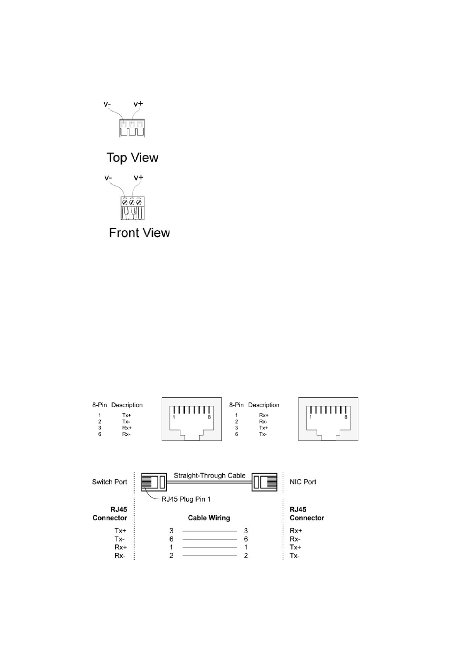
The two left-most contacts of the 3-contact terminal block connector on
EDS’s top panel are used for EDS’s DC or AC inputs. Top and front
views of one of the terminal block connectors are shown here.
STEP 1: Insert the negative/positive DC wires
into the V-/V+ terminals.
STEP 2: To keep the DC wires from pulling
loose, use a small flat-blade screwdriver to
tighten the wire-clamp screws on the front of
the terminal block connector.
STEP 3: Insert the plastic terminal block
connector prongs into the terminal block
receptor, which is located on EDS’s top panel.
Communication Connections
EDS-205 has five 10/100BaseT(X) Ethernet ports.
10/100BaseT(X) Ethernet Port Connection
The 10/100BaseT(X) ports located on EDS’s front panel are used to
connect to Ethernet-enabled devices.
Below we show pinouts for both MDI (NIC-type) ports and MDI-X
(HUB/Switch-type) ports, and also show cable wiring diagrams for
straight-through and cross-over Ethernet cables.
RJ45 (8-pin, MDI) Port Pinouts RJ45 (8-pin, MDI-X) Port Pinouts
RJ45 (8-pin) to RJ45 (8-pin) Straight-Through Cable Wiring