Installation instructions rd-iq installation, Check error display, Replace front panel – TREND RD-IQ User Manual
Page 7: Adjust contrast, Configure controllers
RD-IQ Room Display Installation Instructions TG200492 Issue 1/G 16/01/07
7
Installation Instructions
RD-IQ
INSTALLATION
(continued)
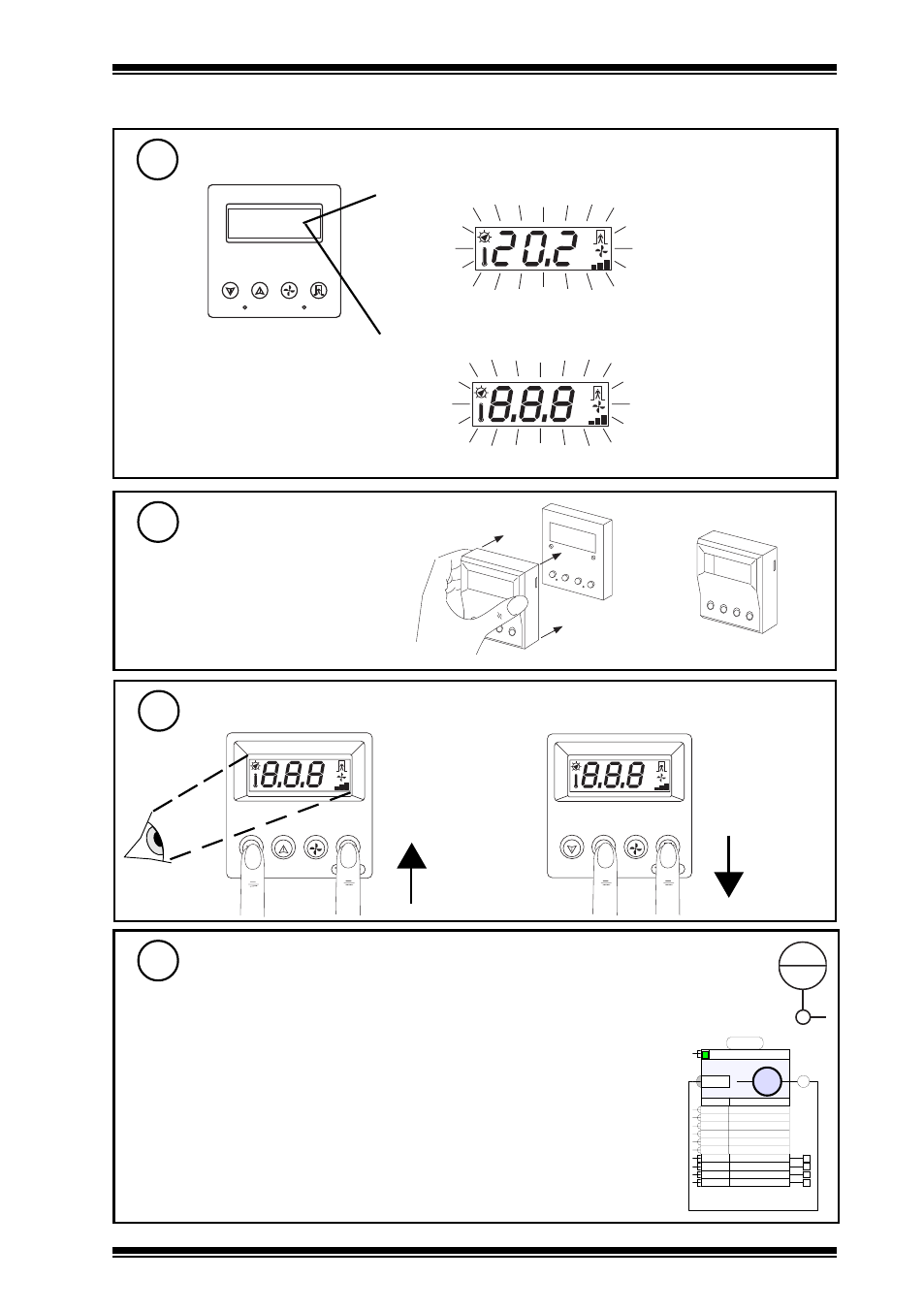
Check Error Display
15
Replace Front Panel
16
S P
E N G
1
2
3
4
° C
° F
A U T O
check RD-IQ PINs match and PIN level; set up PIN
(a) Module does not exist (Sy, Ka, Kb, Kc)
continuous
check module numbers in IQ
° C
° F
A U T O
continuous
or (b) PIN error (change of value)
e.g.
2
Sensor 9
S9
INTERNAL
S
V
S9V
DegC
Units
0
High Alarm Limit
0
Low Alarm Limit
0
High Alarm Delay
0
Low Alarm Delay
0
Out.Limits Delay
0
Read Alarm Delay
Disabled Read Alarm
Disabled Out. Limits Alarm
Disabled Low Alarm
Disabled High Alarm
Adjust Contrast
17
° C
° F
° C
° F
Configure Controllers
18
The IQ strategy must comply with default
modules used by RD-IQ or with those changed
to in step 12, ‘Engineer Communication’.
Defaults:
Local Temperature
S9
Setpoint
K1
Occupation Status
K6
Fan Speed Status
K7
PIN
none
Note that the strategy must not overwrite
the local temperature value. For example in
IQ1, 2, if the default S9 is used, sensor 9
must be an internal sensor sourced from
node 9 (the sensor should be sequenced)
S9
I
9
In IQ3 the modules must be
created in SET, the sensor
must have its output looped
back to its input, and the
sensor must be sequenced