Installation instructions rd-iq installation, Connect to iq, Check start up reset – TREND RD-IQ User Manual
Page 3: Engineer temperature offset, Connect input supply, Switch on power, Mount unit
RD-IQ Room Display Installation Instructions TG200492 Issue 1/G 16/01/07
3
Installation Instructions
RD-IQ
INSTALLATION
(continued)
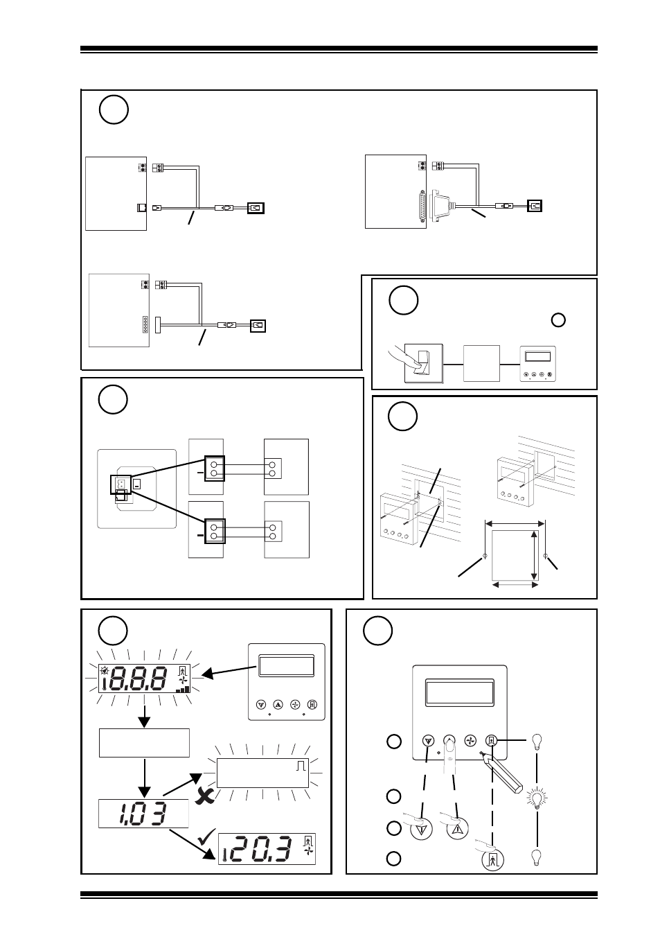
Connect to IQ
(continued)
5
* If one side of the 24 Vac supply is connected to 0 V,
that side must be connected to the RD - (negative) terminal
Check Start Up Reset
9
S P
E N G
1
2
3
4
° C
° F
A U T O
Firmware version
Engineer Temperature Offset
10
S P
E N G
1
2
3
4
if required to offset sensor value
a
b
c
d
or
ENG + 2
default = 0
° C
A U T O
communications
failure
RD/SDU-ADAPTOR IQ1xx+
RD/SDU-ADAPTOR IQ1xx
° C
continuous
For early IQ21x, early IQ22x, IQ250, IQ251, later IQ1xx
For early IQ1xx with 5 in line RS232
For early IQ1xx with 25 way D type RS232
RD/SDU-ADAPTOR IQ2xx
RJ11
IQ2xx
RJ11
RJ11
2 terminal
power
signal
24 Vdc
auxiliary
5 in line
IQ1xx
RJ11
RJ11
2 terminal
power
signal
24 Vdc
auxiliary
IQ1xx
RJ11 RJ11
2 terminal
power
signal
For controllers without power from RJ11, use of adapter,
in addition to RJ11 to RJ11 standard cable, facilitates
connection of power from IQ’s 24 Vdc auxiliary supply
Connect Input Supply
6
+
if early IQ21x, early IQ22x, IQ251, IQ250,
IQ1xx controllers and not using adapters
+
+24 Vdc
24 Vdc Supply
RD
0 Vdc
+
+24 Vac (L)
24 Vac Supply
RD
+24 Vac (N)
24 Vdc
10 mA
24 Vac
10 mA
*
24 Vdc
auxiliary
25 way
Switch on Power
7
if RD separately supplied as in 6
O
I
S P
E N G
1
2
3
4
24 V
RD
standard UK electric
back box
or panel
60 mm
46 mm
50 mm
M3.5 screw
M3.5 screw
60 mm
2 off M3.5 x
35 mm screws
provided
Note that the IQ controller may be connected
while powered; if not power up controller.
Mount Unit
8