Rd-iq installation instructions, Installation, Connect to iq – TREND RD-IQ User Manual
Page 2: Remove front panel, Route cable(s), Requirements, Ij k
RD-IQ
Installation Instructions
RD-IQ Room Display Installation Instructions TG200492 Issue 1/G 16/01/07
2
S P
E N G
1
2
3
4
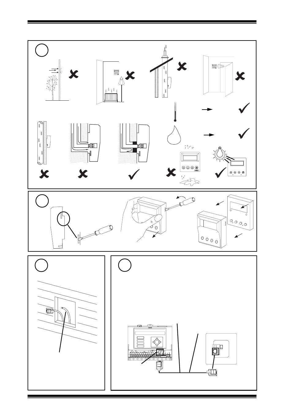
INSTALLATION
(continued)
Connect to IQ
5
Remove Front Panel
3
Route Cable(s)
4
Requirements
(continued)
2
i
j
k
H O
2
-10 °C
+14 °F
+40 °C
+104 °F
0 %RH
90 %RH
h
e
d
f
g
b
a
c
Power cable only required for
IQs (early IQ21x early IQ22x,
IQ250, IQ251, IQ1xx) if not
using special adaptors - see
step 6
if IQ is IQ3, IQ2xx, or IQ1xx (firmware v4.7 or greater)
Note that RD-IQ cannot be connected to a controller with local
supervisor port already used (e.g. wireless sensor receiver
XW/R/IQ, NDP, IQView (RS232), or local PC) or to /ADL, /ATM
or XNC220 controllers.
Note that sUperv port addr should set to zero (default)
1 2 3 4 5 6 7 8 9 10
A
B
C
D
DP
V
24V
+
IQ2xx
RJ11
local supervisor
port
RJ11
maximum distance 25 m (28 yds)
RD/SDU-IQ2COMMSCABLE/3M
Standard cables connect signal plus power for all IQ3s, IQ204,
later IQ21x, later IQ22x, IQ23x, IQ241/242, IQ246
l
Note that the IQ controller may be connected while powered;
if not power up controller.