Qphy-lpddr2 software option – Teledyne LeCroy QPHY-LPDDR2 User Manual
Page 23
QPHY-LPDDR2 Software Option
QPHY-LPDDR2-OM-G Rev B
23
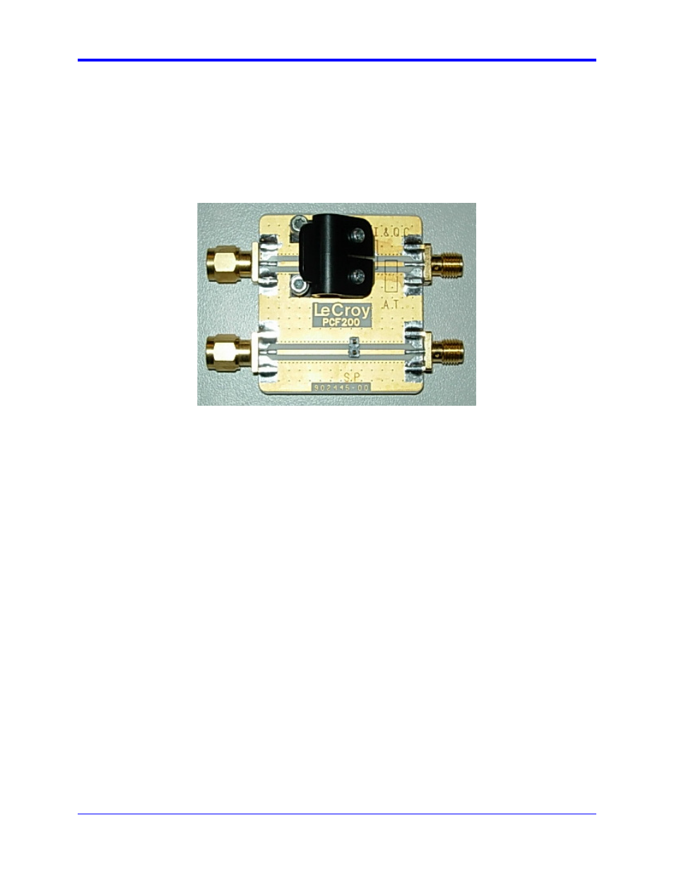
PCF200 Fixture Overview
Major components of the PCF200 fixture are shown in the following figure:
•
SMA male connector Fast Edge input.
•
SMA female connector output to AUX IN for 50-ohm termination.
•
Clip for connection of Solder-In probes.
•
2-pins header for connection of Square-Pin probes.
Figure 14. PCF200 Deskew Fixture
A SMA male to BNC male 50-ohm cable is required to perform the calibration.
System assembly is accomplished in the following steps:
1.
Connect the BNC end of the 50 Ohm cable to the oscilloscope AUX IN.
2.
Connect the SMA end of the 50 Ohm cable to the SMA female connector on the PCF200 fixture.
3.
Connect the PCF200 SMA male connector to the oscilloscope Fast Edge SMA output.
The SMA connections should be torqued with an RF torque wrench and must be properly tightened.
Probe Connection to PCF200
The PCF200 provides multiple probe connectors for various kinds of probes. There are 2 circuits
depending on the type of probes to calibrate:
•
The upper circuit is for Solder-In (SI) and Quick-Connect (QC) probes. This circuit can also be
used for AT probes using the designated area to apply the probe tips.
•
The lower circuit is for Square-Pin (SP) probes.