Teledyne LeCroy PMC2PCI-64 User Manual
Page 8
7
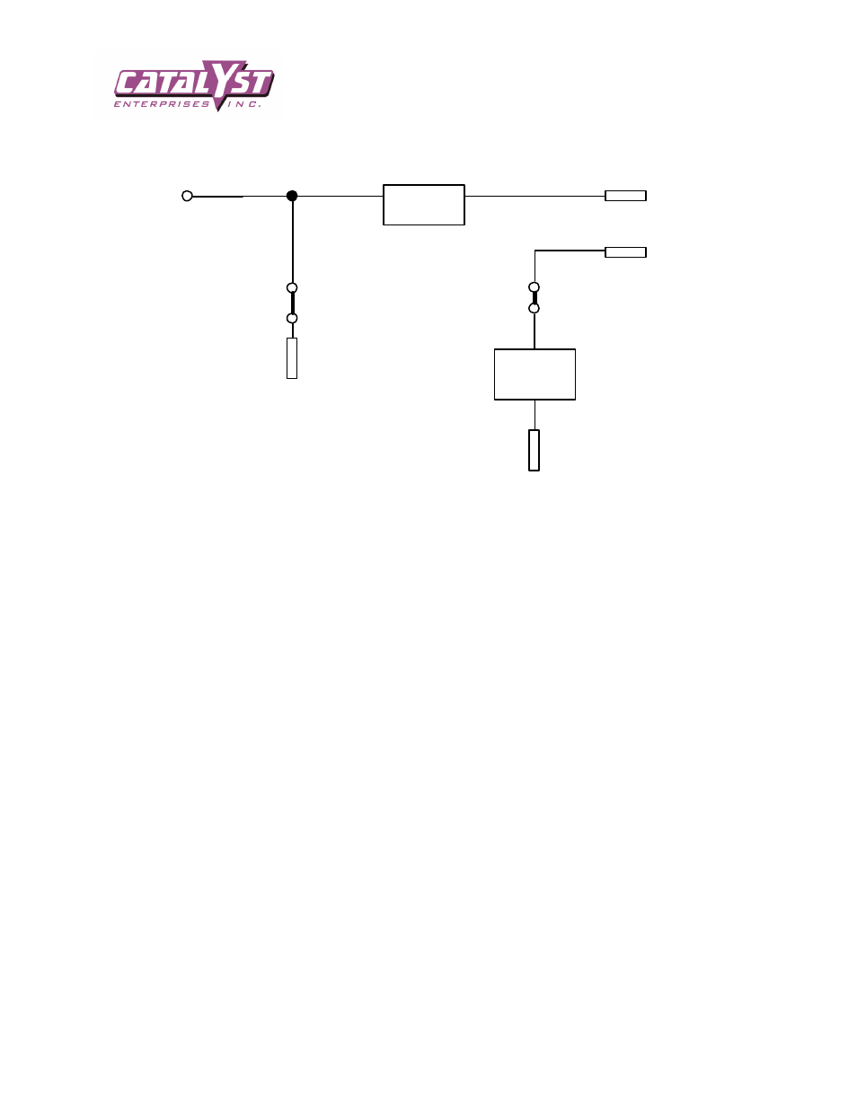
The following diagram indicates the interconnection of the Unit-Under-Test voltages to bus voltages and the
external voltages:
+5VE
to Unit-Under-Test
ON-OFF
Circuitry
+5BV
+VIOB
JP6
JP10
+5V from the Bus
ON-OFF
Circuitry
+VIO from bus (+5v plane)
As you can see, there will be a conflict in case the external supply is connected while the jumper is still in
place. This circuit is repeated for each of the 4 voltages.
If you are using external power supplies do not forget to connect the Ground (GND) signals. If your external
power supply outputs are not isolated, make sure the ground of the PC (containing the extender board) and the
ground of the power supply are at the same voltage level with respect to a common point, before connecting
the GND signal.
Note: Be sure to remove JP10 if the VIO and +5V on your board are on the same voltage plane.