Teledyne LeCroy PMC2PCI-64 User Manual
Page 10
9
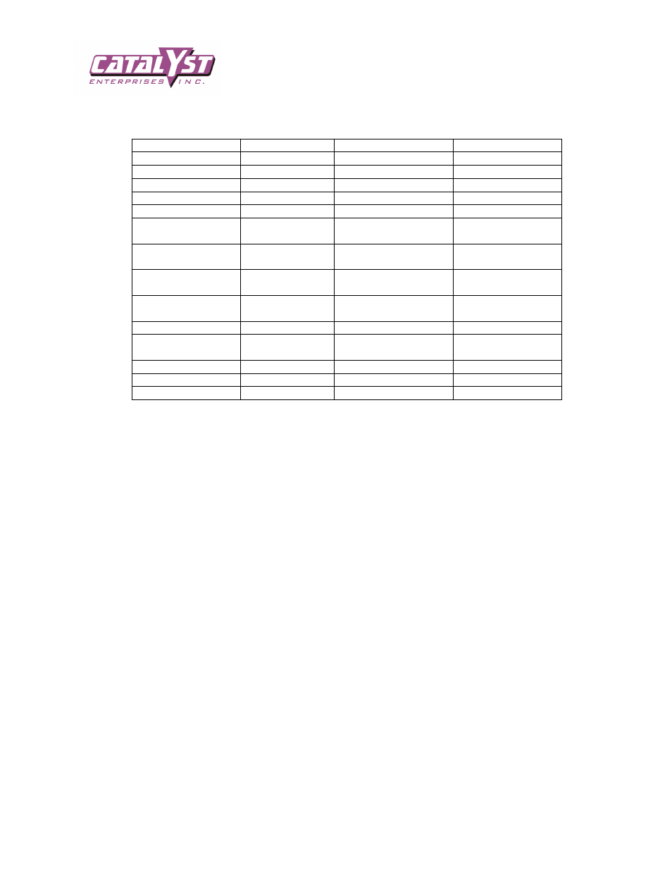
JUMPER TABLE
JUMPER Function
PCI532/PCI332
PCIX6432/PCIX6466-3 PMC2PCI-64
Isolate +5V
JP6
JP6
JP6
Isolate +12V
JP4
JP4
JP4
Isolate +3.3V
JP7
JP7 (Change source)*
JP7
Isolate –12V
JP5
JP5
JP5
Isolate VIO
JP10
JP10
JP10
Change +5V Current
Limit to 1A
JP8
JP8
JP8
+5V Current
Measurement
J3
J3
J3
+12V Current
Measurement
N/A
J4
J4
+3.3V Current
Measurement
N/A
J5
J5
External Control
JP3
JP3
JP3
5V=> 3V Signal
Level Conversion
N/A
JP9
JPX
BUS MODE
N/A
N/A
JPN2, JPN3, JPN4
AUX3.3
N/A
JP12
N/A
PME
N/A
JP11
N/A
AUXILIARY POWER CONNECTOR PIN-OUT
PCI532 and PCI332 power connector for the external power supply is different than the one used for
PMC2PCI and PCIX-6432. The PCI532 connector is marked as indicated, but the other connectors are
intended for use with ribbon cable and are not marked on the board. The following pin-out can be used if the
user wants to arrange his own interface. Please note that each signals is divided and placed symmetrically on
both sides of the connector, this will allow the connector to be plugged in either direction and make proper
connection.
SIGNAL PIN SIGNAL
+5EV
1
2
+5EV
+5EV
3
4
+5EV
+5VS
5
6
+3VS
+3EV
7
8
+3EV
+12VS
9
10
-12EV
N.U.
11
12
SW
-12EV
13
14
+12EV
SW
15
16
N.U.
-12EV
17
18
+12VS
+3EV
19
20
+3EV
+3VS
21
22
+5VS
+5EV
23
24
+5EV
+5EV
25
26
+5EV
The EV signals are the voltage signals, remember not to bring in any external voltages until you reconfigure
the jumpers for external supply mode. The VS signals are sense signals for compensating any voltage lose in
the cable. The SW is an open collector signal and it is the sane as the switch or jumper JP3 to turn the board
on and off.