System Sensor RR1 User Manual
Page 3
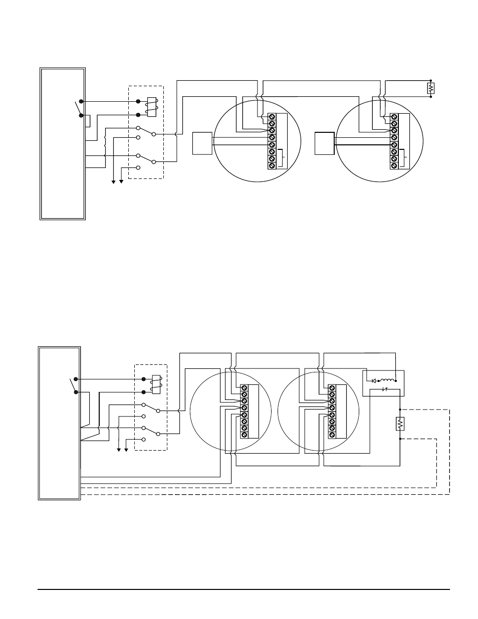
Figure 4. RR1 module with alarm relay and 4-wire smoke detectors:
Figure 3. RR1 module with alarm relay and 2-wire smoke detectors:
A78-2336-12
A78-2336-11
EOL
+
+
–
A
+
RA400Z
A
-
+
–
+
+
–
A
+
A
-
RA400Z
+
–
P
W
R
P
W
R
ALARM
RELAY
(N/O contact)
OUTPUT
UL LISTED
CONTROL
PANEL
INITIATING
LOOP
T1
RED
BLK
BLUE
ORG
PURPLE
YELLOW
BROWN
WHITE
T2
T8
T6
T3
T5
T4
T7
+
–
+
+
–
–
Not
Used
Not
Used
AUX.
POWER
SUPPLY
The power reversal relay module does not provide supervision.
All supervision is provided by the interconnected control unit.
POWER REVERSAL
RELAY MODULE (RR1)
To auxiliary power/IAC/Bell output or
any UL listed regulated power supply
listed for fire protective signaling use.
(polarity shown with panel in alarm).
OPTIONAL CLASS A WIRING
EOL RESISTOR
SPECIFIED BY
PANEL
MANUFACTURER
EOL POWER
SUPERVISION
RELAY (SHOWN
ENERGIZED)
A77-716 12/24V
POWER
TO
DETECTORS
UL LISTED
CONTROL
PANEL
INITIATING
LOOP
+
+
T1
RED
BLK
BLUE
ORG
PURPLE
YELLOW
BROWN
WHITE
T2
T8
T6
T3
T5
T4
T7
–
–
P
W
R
A
U
X
P
W
R
A
U
X
+
+
–
A
A
NC
C
NO
+
INITIATING
LOOP
+
–
A
A
NC
C
NO
}
The power reversal relay module does not provide supervision.
All supervision is provided by the interconnected control unit.
POWER REVERSAL
RELAY MODULE (RR1)
To auxiliary power/detector power/IAC/Bell
output or any UL listed regulated power supply
listed for fire protective signaling use.
(polarity shown with panel in alarm).
ALARM
RELAY
(N/O contact)
OUTPUT
M500-12-00
3
I56-1168-02
NOTE: If optional Class A wiring is used, second power reversal relay module (RR1) must be added to enable concurrent
loop polarity reversal.