System Sensor RRS-MOD User Manual
Page 4
UL LISTED
ALARM
CONTROL
PANEL
AUX (+)
PGM 2
PGM 1
+
–
AUX
AUX
DSC POWER 832
PURPLE
YELLOW
ORANGE
RED
BLACK
BROWN
WHITE
EOL
1 + IN
2 + OUT
3 - IN/OUT
4 N.O.
5 C
1 + IN
2 + OUT
3 - IN/OUT
4 N.O.
5 C
5.6
KΩ*
*NOTE: 5.6KΩ resistor must be rated for 1/4W or greater. Must be present for panel to reset.
D500-44-00
4
I56-2203-005
© System Sensor 2009
System Sensor warrants its enclosed product to be free from defects in materials and
workmanship under normal use and service for a period of three years from date of
manufacture. System Sensor makes no other express warranty for the enclosed product.
No agent, representative, dealer, or employee of the Company has the authority to in-
crease or alter the obligations or limitations of this Warranty. The Company’s obligation
of this Warranty shall be limited to the replacement of any part of the product which
is found to be defective in materials or workmanship under normal use and service
during the three year period commencing with the date of manufacture. After phoning
System Sensor’s toll free number 800-SENSOR2 (736-7672) for a Return Authorization
number, send defective units postage prepaid to: System Sensor, Returns Department, RA
#__________, 3825 Ohio Avenue, St. Charles, IL 60174. Please include a note describing
the malfunction and suspected cause of failure. The Company shall not be obligated to
replace units which are found to be defective because of damage, unreasonable use,
modifications, or alterations occurring after the date of manufacture. In no case shall the
Company be liable for any consequential or incidental damages for breach of this or any
other Warranty, expressed or implied whatsoever, even if the loss or damage is caused by
the Company’s negligence or fault. Some states do not allow the exclusion or limitation of
incidental or consequential damages, so the above limitation or exclusion may not apply
to you. This Warranty gives you specific legal rights, and you may also have other rights
which vary from state to state.
Three-Year LimiTed WarranTY
TesTing
Before testing, notify the proper authorities that the system is undergoing
maintenance and will temporarily be out of service.
Test in accordance with NFPA 72 test methods, inspections, and testing frequency.
1. Confirm that all smoke detectors connected to the RRS-MOD module(s)
contain a sounder and the sounders are activated upon power reversal.
2. Initiate an alarm with one of the smoke detectors connected to the RRS-
MOD module using any approved test method. In the alarm state, all the
detectors connected to the RRS-MOD module must be sounding their
sounders.
3. Reset the system from the control panel. All smoke detector sounders
should be silent.
4. If the fire alarm panel also functions in burglary, initiate a burglary alarm
and ensure the smoke detectors do not sound.
S0108-02
Figure 8. ConneCTing 2WTa-B smoke deTeCTors To dsC PoWer 832 ConTroLs us-
ing rrs-mod moduLe WiTh Pgm ouTPuT:
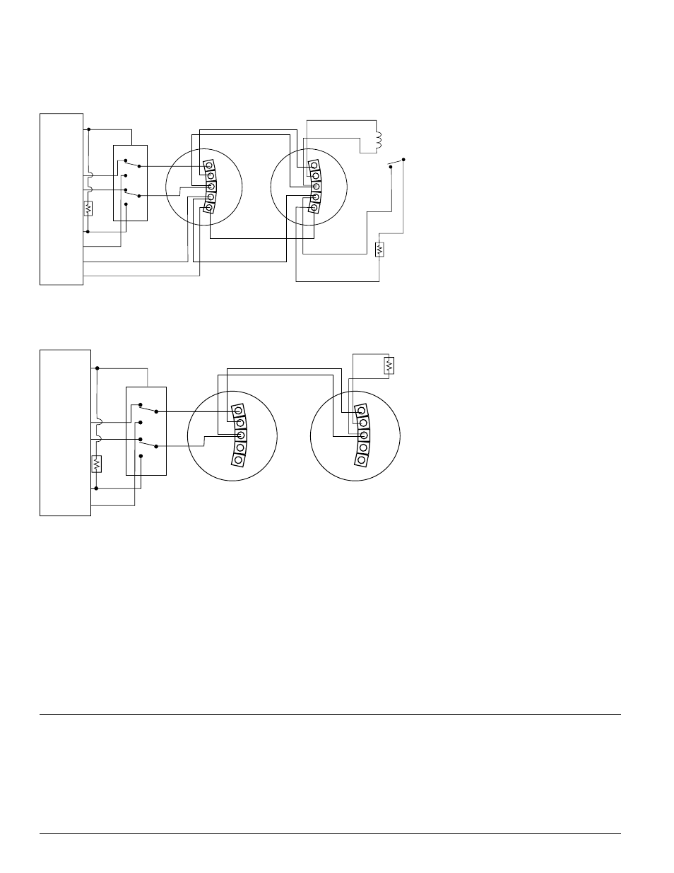
Figure 7. ConneCTing 4WTa-B, 4WTar-B, and 4WiTar-B smoke deTeCTors To dsC
PoWer 832 ConTroLs using rrs-mod moduLe WiTh Pgm ouTPuT:
UL LISTED
ALARM
CONTROL
PANEL
AUX (+)
PGM 2
PGM 1
+
–
AUX
AUX
ZONE
ZONE (COM)
+
–
DSC POWER 832
PURPLE
YELLOW
ORANGE
RED
BLACK
BROWN
WHITE
EOL
EOL RELAY
(SHOWN ENERGIZED)
1 + IN
2 + OUT
3 - IN/OUT
4 N.O.
5 C
1 + IN
2 + OUT
3 - IN/OUT
4 N.O.
5 C
5.6
K� *
*NOTE: 5.6K� resistor must be rated for 1/4W or greater. Must be present for panel to reset.
All smoke detectors on the 4-wire fire zone will
be synchronized in alarm and will sound 1 sec
ON, 1 sec OFF only from a fire alarm event.
noTe:
• Program zone section attributes for bell
output to be pulsing.
• PGM2 must be programmed for sensor
reset.
• PGM1 must be programmed as Burglary
and Fire Bell Output (01) with ON, ON,
OFF attributes.
• RRS-MOD switch must be set to OFF (fac-
tory default setting).
All smoke detectors on the 2-wire fire zone will
be synchronized in alarm, and will sound 1 sec
ON, 1 sec OFF only from a fire alarm event.
NOTE:
• Program zone section attributes for bell
output to be pulsing.
• PGM2 must be programmed for 2-wire
smoke zone (04). Jumper J1 on the main
board must be removed.
• PGM1 must be programmed as Burglary
and Fire Bell Output (01) with ON, ON,
OFF attributes.
• RRS-MOD switch must be set to OFF (fac-
tory default setting).
ConneCTion diagrams WiTh dsC PoWer 832 PaneLs
S0107-02