System Sensor RRS-MOD User Manual
Page 2
D500-44-00
2
I56-2203-005
NOTE: Please refer to Figures 5 and 6 for Ademco Vista panels and Figures 7 and 8 for DSC Power 832 panels.
S0101-01
S0102-00
S0103-01
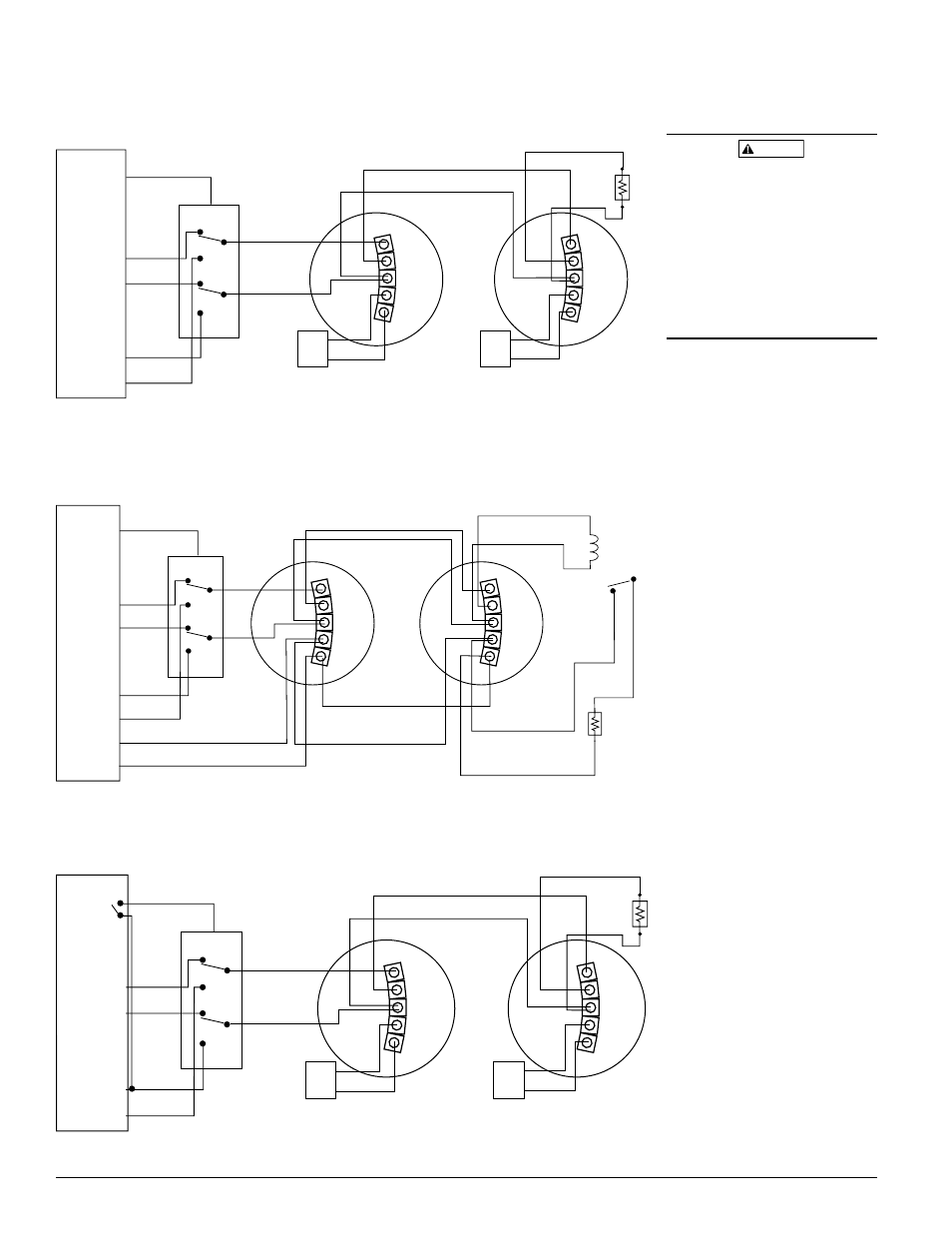
Figure 1. 2-Wire sYsTem Triggered From aLarm/BeLL ouTPuT:
Figure 2. 4-Wire sYsTem Triggered From aLarm/BeLL ouTPuT:
Figure 3. 2-Wire sYsTem Triggered From aLarm reLaY ConTaCT:
EOL
OPTIONAL
REMOTE
ANNUNCIATOR
(RA400Z/RA100Z)
OPTIONAL
REMOTE
ANNUNCIATOR
(RA400Z/RA100Z)
+
–
UL LISTED
ALARM
CONTROL
PANEL
2–WIRE
INITIATING
DEVICE
CIRCUIT
PURPLE
T+
+
–
+
–
AUX POWER
YELLOW
IN+
ORANGE
IN–
RED
PWR+
BLACK
PWR–
BROWN
OUT+
WHITE
OUT–
1 + IN
2 + OUT
3 - IN/OUT
4 RA+
5 RA-
1 + IN
2 + OUT
3 - IN/OUT
4 RA+
5 RA-
+
–
BELL/
ALARM
CIRCUIT
(positive signal
in alarm state)
EOL
UL LISTED
ALARM
CONTROL
EOL RELAY
(SHOWN ENERGIZED)
PANEL
DETECTOR
POWER
+
–
+
–
AUX POWER
OR
DETECTOR
POWER
INITIATING
DEVICE
CIRCUIT
+
–
BELL/ALARM
CIRCUIT
(positive signal
in alarm state)
PURPLE
T+
YELLOW
IN+
ORANGE
IN–
RED
PWR+
BLACK
PWR–
BROWN
OUT+
WHITE
OUT –
1 + IN
2 + OUT
3 - IN/OUT
4 N.O.
5 C
1 + IN
2 + OUT
3 - IN/OUT
4 N.O.
5 C
ALARM
RELAY
(NO Contact)
UL LISTED
ALARM
CONTROL
PANEL
2–WIRE
INITIATING
DEVICE
CIRCUIT
PURPLE
T+
+
–
+
–
AUX POWER
YELLOW
IN+
ORANGE
IN–
RED
PWR+
BLACK
PWR–
BROWN
OUT+
WHITE
OUT–
EOL
OPTIONAL
REMOTE
ANNUNCIATOR
(RA400Z/RA100Z)
OPTIONAL
REMOTE
ANNUNCIATOR
(RA400Z/RA100Z)
+
–
1 + IN
2 + OUT
3 - IN/OUT
4 RA+
5 RA-
1 + IN
2 + OUT
3 - IN/OUT
4 RA+
5 RA-
+
–
CAUTION
When using the RRS-MOD with model
2WTA-B, do not mix the 2WTA-B with
other model smoke detectors and dry
contact closure devices, including me-
chanical heat detectors, manual pull
stations and waterflow switches. Such
mixing can cause a direct short on the
auxiliary power terminals, damaging the
control panel’s internal circuitry and/or
damaging devices connected to the initi-
ating device circuit.