System Sensor RR2 User Manual
Page 2
D500-44-00 2 I56-1683-02
NOTE: If your panel configuration does not match any of the following wiring diagrams, please contact System Sensor
technical services at 1-800-SENSOR2 for assistance. Please refer to Figures 5 and 6 for Ademco Vista panels and Figure
7 for DSC Power 832 panels.
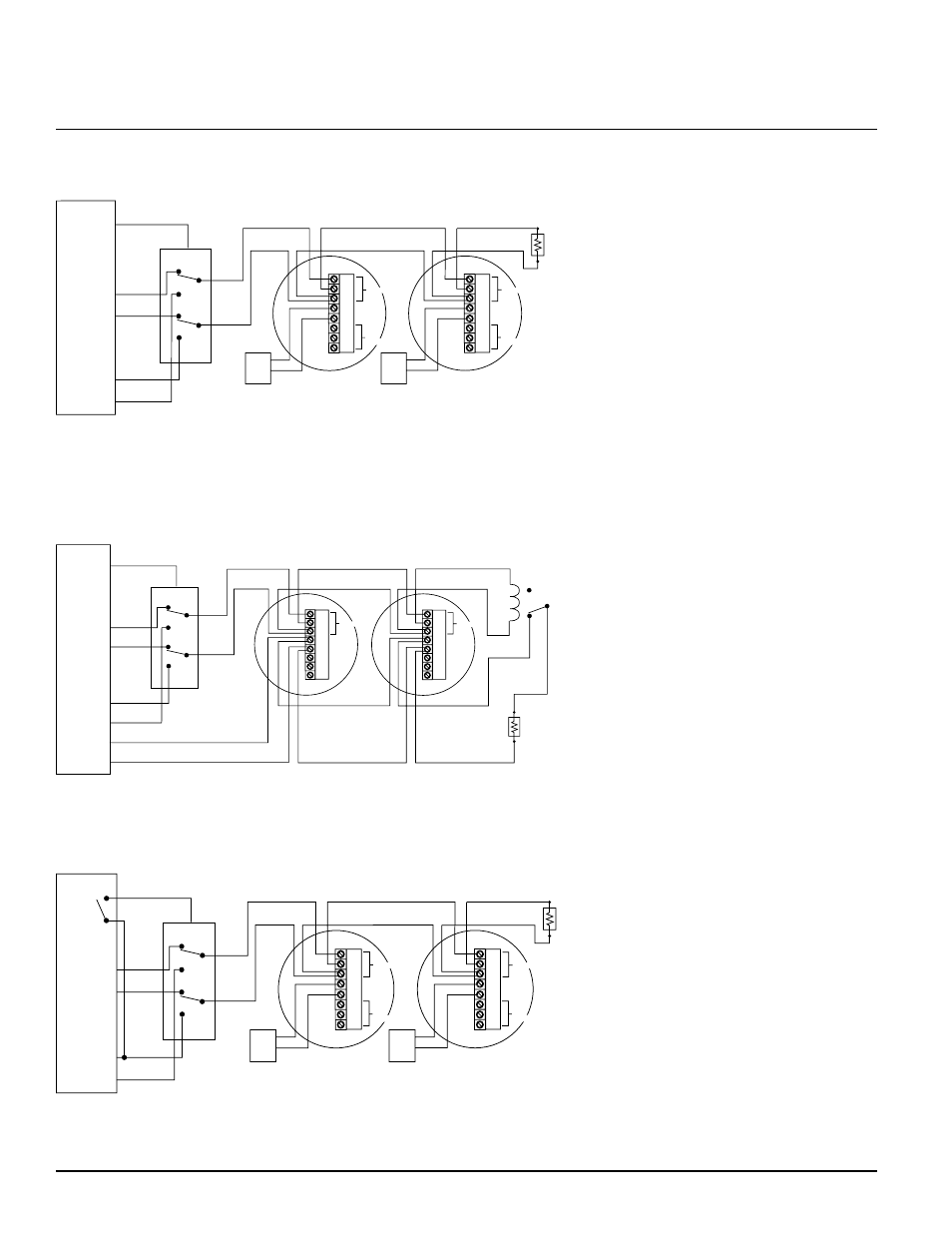
NOTE: If optional Style A (Class B) wiring is used, a second RR2 module must be added to enable concurrent loop
polarity reversal.
NOTE: If optional Style A (Class B) wiring is used, a second RR2 module must be added to enable concurrent loop
polarity reversal.
S0124-00
S0125-00
S0126-00
Figure 1. 2-Wire system triggered from IAC/bell circuit:
Figure 2. 4-Wire system triggered from IAC/bell circuit:
Figure 3. 2-Wire system triggered from alarm relay contact:
EOL
+
+
–
A
+
RA400Z
A
-
+
–
BELL/
ALARM
CIRCUIT
(positive signal
in alarm state)
UL LISTED
ALARM
CONTROL
PANEL
INITIATING
CIRCUIT
PURPLE
T+
+
–
+
–
AUX POWER
YELLOW
IN+
ORANGE
IN–
RED
PWR+
BLACK
PWR–
BROWN
OUT+
WHITE
OUT–
Power
Not
Used
+
+
–
A
+
RA400Z
A
-
+
–
Power
Not
Used
EOL
+
+
–
A
A
UL LISTED
ALARM
CONTROL
PANEL
DETECTOR
POWER
+
–
+
–
AUX POWER
OR
DETECTOR
POWER
Power
INITIATING
CIRCUIT
+
–
+
+
–
Power
NC
NO
C
Aux
A
A
NC
NO
C
Aux
BELL/ALARM
CIRCUIT
(positive signal
in alarm state)
PURPLE
T+
YELLOW
IN+
ORANGE
IN–
RED
PWR+
BLACK
PWR–
BROWN
OUT+
WHITE
OUT–
EOL
+
+
–
A
+
RA400Z
A
-
+
–
ALARM
RELAY
(NO Contact)
UL LISTED
ALARM
CONTROL
PANEL
INITIATING
CIRCUIT
+
–
+
–
AUX POWER
Power
Not
Used
+
+
–
A
+
RA400Z
A
-
+
–
Power
Not
Used
PURPLE
T+
YELLOW
IN+
ORANGE
IN–
RED
PWR+
BLACK
PWR–
BROWN
OUT+
WHITE
OUT–