Inches. secure module to box as shown in figure 4 – System Sensor 2W-MOD2 User Manual
Page 2
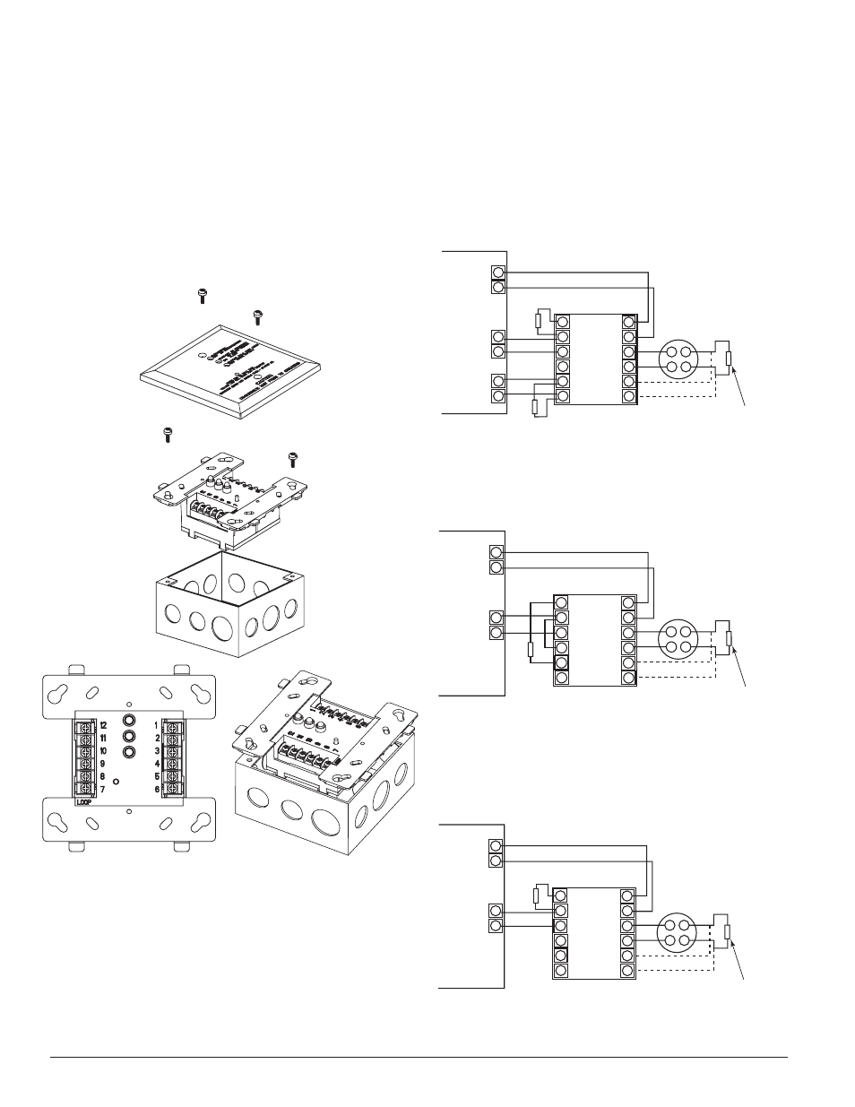
Wiring Diagram
Install module wiring in accordance with appropriate wir-
ing diagrams (Figures 5 - 7). Reset is performed through
power inputs 1 and 2.
Figure 5. The Module Wiring: maintenance signal is
sent to a separate zone.
Control Panel
2W-MOD2
Aux. or
Smoke
Power
Fire Zone
Trouble Zone
Panel EOL
Panel EOL
12
11
10
9
8
7
1
2
3
4
5
6
Loop Style D wiring
3.9 K
�
EOL (must not be
used for Style D)
A2143-10
+
–
+
–
Two-wire listed smoke
detectors. Do not mix
models on the same loop.
Only one 2WTR–B per loop.
Only one 2WTA–B per loop,
unless used with the RRS–MOD.
ALL CIRCUITS ARE SUPERVISED
AND MUST BE POWER LIMITED.
S0232-01
Figure 6. The Module Wiring: maintenance signal is
indicated at the panel as a fire trouble.
Control Panel
2W-MOD2
Aux. or
Smoke
Power
Fire Zone
Panel EOL
12
11
10
9
8
7
1
2
3
4
5
6
+
–
Loop Style D wiring
ALL CIRCUITS ARE SUPERVISED
AND MUST BE POWER LIMITED.
Two-wire listed smoke
detectors. Do not mix
models on the same loop.
Only one 2WTR–B per loop.
Only one 2WTA–B per loop,
unless used with the RRS–MOD.
3.9 K
�
EOL (must not be
used for Style D)
A2143-10
+
–
S0233-01
Figure 7. The Module Wiring: two-wire detectors to
four-wire panel conversion.
Control Panel
2W-MOD2
Aux. or
Smoke
Power
Fire Zone
12
11
10
9
8
7
1
2
3
4
5
6
+
–
Panel EOL
Loop Style D wiring
3.9 K
�
EOL (must not be
used for Style D)
A2143-10
+
–
Two-wire listed smoke
detectors. Do not mix
models on the same loop.
Only one 2WTR–B per loop.
Only one 2WTA–B per loop,
unless used with the RRS–MOD.
ALL CIRCUITS ARE SUPERVISED
AND MUST BE POWER LIMITED.
S0234-01
For NFPA loop Style D wiring the EOL resistor is provided
internal to the module. An external EOL resistor must
not be connected at the last detector on the loop (see Fig-
ures 5 – 7).
Compatibility Requirements
The 2W-MOD2 is marked with a compatibility/zone identi-
fier as the last digit of a 5 digit code on the back of the unit.
To ensure proper operation, this module shall be connected
to compatible two-wire smoke detectors or the alarm con-
tacts of four–wire i3 series detectors only. (Consult System
Sensor’s 2-wire compatibility guide).
Figure 4. Mounting module
Mounting
Install in a dry indoor location. The 2W-MOD2 Mainte-
nance Module mounts directly to 4 inch square electrical
boxes (supplied by installer). The box must have a mini-
mum depth of 2
1
/
8
inches. Secure module to box as shown
in Figure 4.
D500-46-00
2
I56-2174-004
S0235-00
S0237-00
S0238-00