System Sensor 2551HR Plug-in Intelligent User Manual
Page 2
D500-41-00
2
I56-1437-00
d. Turn the sensor clockwise until it drops into place.
e. Continue turning the sensor clockwise until it locks
into place.
WARNING
Sensor will not detect smoke if dust cover is installed.
2. Tamper-proof feature:
The sensor bases include a tamper-proof feature that,
when activated, prevents removal of the sensor without
the use of a tool. See the installation instruction manual
for the sensor base for details in using this feature.
3. After all sensors have been installed, apply power to the
control unit.
4. Test all sensors per the TESTING section of this manual.
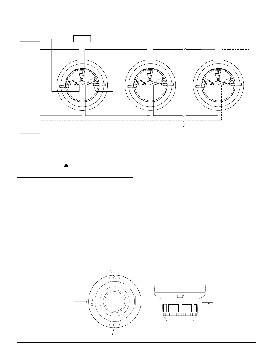
3
2
1
3
2
1
3
2
1
+
-
-
+
U.L. LISTED COMP
A
TIBLE
CONTROL
P
ANEL
CLASS A OPTIONAL WIRING
REMOTE ANNUNCIATOR
+
-
CAUTION: Do not loop wire under terminal 1 or 2.
Break wire run to provide supervision of connections.
A78-1253-01
Figure 1. Wiring Diagram:
Figure 2. Views showing position of test magnet (model 2551HR shown):
A78-1410-02
Testing
Before testing, notify the proper authorities that the smoke
sensor system is undergoing maintenance, and therefore
the system will temporarily be out of service. Disable the
zone or system undergoing maintenance to prevent un-
wanted alarms.
Sensors must be tested after installation and periodic main-
tenance. The sensor may be tested in the following ways:
A. Test Magnet (Model No. M02-04-00)
1. Place the magnet against the cover opposite the test
module socket to activate the test feature (see Figure 2).
2. The LEDs should latch on within 10 seconds indicat-
ing alarm and annunciating the panel.
B. Test Module (Model No. MOD400R)
The MOD400R is used with your DMM or voltmeter to
check the sensor sensitivity as described in the
MOD400R’s manual.
LED
LED
TEST MODULE
SOCKET
TEST
MAGNET
PAINTED
SURFACE
TEST
MAGNET