7] detector cleaning procedures, 1] air filters, 2] photo detector board – System Sensor DH100ACDCLWP User Manual
Page 7
[7] Detector Cleaning Procedures
Notify the proper authorities that the smoke detector system is
undergoing maintenance, and that the system will temporarily be
out of service. Disable the zone or system undergoing mainte-
nance to prevent unwanted alarms and possible dispatch of the
fire department.
[7.1] Air Filters
1. Turn off power to the system.
2. Remove and inspect sampling tube filters.
3. If filters are heavily coated with dirt, replace them with new
filters. If they are not heavily coated, use a vacuum cleaner or
compressed air nozzle to remove dust, then reinstall the filters.
[7.2] Photo Detector Board
1. Remove the screen by gently grasping on each side and pull-
ing straight off.
2. Lift the photo chamber in the same fashion. Vacuum the
screen and cover. Use clean, compressed air to loosen and
blow out any remaining debris. Replacement screens (S08-39-
01) are available.
3. Vacuum photo chamber, then use clean compressed air to
blow area clean.
4. Replace the chamber by pressing it onto the base. Press the
screen into place. It should fit tightly on the chamber.
[8.0] Board Replacement
[8.1] Detector Board Replacement (part no. A5190)
1. Remove the two detector board mounting screws.
2. Pull gently on the board to remove it.
3. To replace the board, align the board mounting features, holes,
and the interconnect terminals. Push the board into place.
4. Secure board with the two mounting screws.
[8.2] Power Board replacement (part no. A5064)
1. Disconnect wiring from the terminal block.
2. Remove the two power board mounting screws.
3. Pull gently on the board to remove it.
4. To replace the board, align the board mounting features, holes,
and the interconnect terminals. Push the board into place.
5. Secure board with the two mounting screws.
6. Re-connect wiring to terminal block.
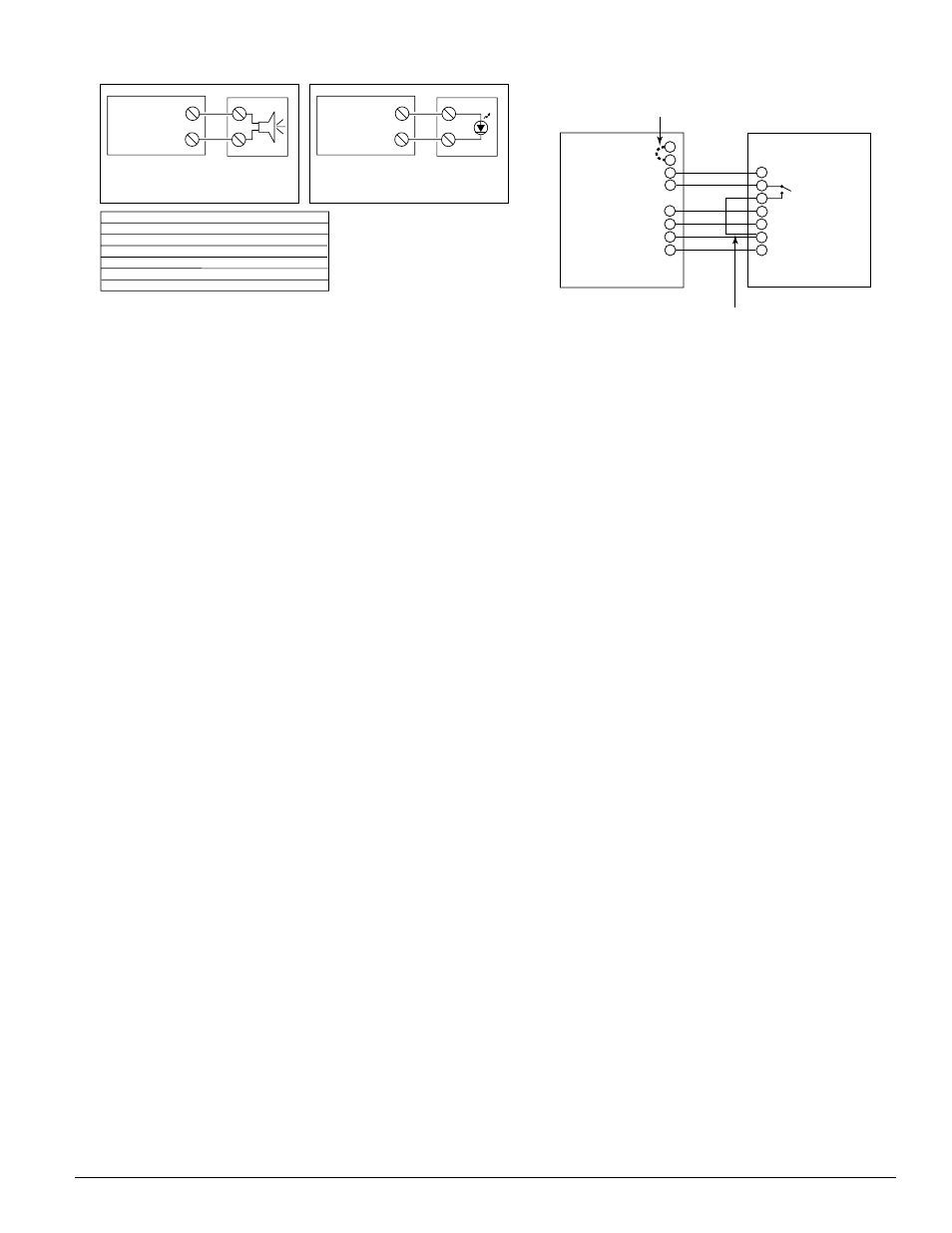
ALARM SIGNAL (+)
AUX POWER (–)
15
20
(+)
(–)
DUCT DETECTOR
DH100ACDCLWP
PA400 (OPTIONAL)
AUDIBLE ALERT
ALARM SIGNAL (+)
AUX POWER (–)
15
20
(+)
(–)
DUCT DETECTOR
DH100ACDCLWP
RA400Z (OPTIONAL)
REMOTE (LED)
ANNUNCIATOR
RED
ACCESSORY CURRENT LOADS AT 24 VDC
DEVICE
APA451
PA400
RA400Z
RTS451/RTS451KEY
SSK451
STANDBY
12.5mA Max.
0mA
0mA
12mA*
5mA Max.
ALARM
30mA Max.
15mA Max.
10mA Max.
7.5mA Max.
30mA Max.
*NOTE: When a unit is powered at the 120VAC or 220/240VAC input, any
combination of accessories may be used such that the given accessory loads are:
60 mA or less in the standby state; 110 mA or less in the alarm state.
TROUBLE
n/a
n/a
n/a
n/a
9mA Max.
D200-24-00
7
I56-0056-009R
Figure 11. Wiring diagrams for optional accessories:
H0377-01
15
ALARM SIGNAL
3
14
2
RESET
11
TEST
20
AUX. POWER (-)
19
AUX. POWER (+)
SSK451
FIELD INSTALLED
JUMPER FOR
TEMPORAL PATTERN
SUPERVISORY
CONTACT
NO
FIELD INSTALLED
JUMPER
DH100ACDC
COMMON 3
TEMPORAL SELECT 2
ALARM SIGNAL 1
SUPERVISORY SIGNAL 4
RESET 7
TEST 8
POWER (-) 6
POWER (+) 5
Figure 12. Wiring diagram for
DH100ACDCLWP to SSK451
H0344-00