System Sensor DH100ACDCLWP User Manual
Page 2
[4] Contents Of The Duct Smoke Detector Kit
1. Complete housing base and cover assembly
2. Two #10×1
1
⁄
4
˝ sheet metal screws for mounting
3. Two sampling tube filters
4. One test magnet
5. Drilling template
6. Two foam gaskets
7. Four #6-self tapping mounting screws for the metal sampling
tube and optional exhaust tube extension
8. One sampling tube end cap
9. One plastic telescoping sampling tube
10. One #8 self-tapping screw for the plastic sampling tube
NOTE: For ducts over 1
1
⁄
2
feet, longer sampling tubes must be
ordered to complete the installation. They must be the correct
length for the width of the duct where they will be installed. See
Table 1 on page 3 to determine the sampling tube required for dif-
ferent duct widths.
[5] Installation Sequence
[5.1] Verify Duct Air Flow Direction And Velocity
Model DH100ACDCLWP detectors are designed to be used in air
handling systems having air velocities of 100 to 4000 feet per min-
ute. Be sure to check engineering specifications to ensure that the
air velocity in the duct falls within these parameters. If necessary,
use a velocity meter to check the air velocity in the duct.
[5.2] Select Mounting Orientation
If possible, mount the DH100ACDCLWP with the wiring entry
hole(s) facing downwards, so that all wiring enters the hous-
ing from below. This minimizes the possibility of water entering
around the conduit fittings. Mounting the product with the wiring
entry holes on the uppermost surface should be avoided.
[5.3] Drill The Mounting Holes
Remove the paper backing from the mounting template supplied.
Affix the template to the duct at the desired mounting location.
Make sure the template lies flat and smooth on the duct. Center
punch holes A and B. Drill the holes as indicated on the template.
[5.4] Secure The Detector Housing To The Duct
Slide the foam gaskets over the tube bushings as shown in Figure
2. Use the two 1
1
⁄
4
˝ long sheet metal screws to screw the detector
housing to the duct.
CAUTION: Do not overtighten the screws.
Figure 2. Installation of foam gaskets over sampling
tube bushings:
SCREW HOLES FOR
ATTACHING HOUSING
TO DUCT WORK.
[5.5] Sampling Tube Installation
The sampling tube is identified by a series of air inlet holes on
the tube. A plastic tube is included for ducts up to 18˝ in width.
All other tubes must be ordered separately and resized for the
duct width, as specified in Table 1. It is recommended that the
sampling tube length extend at least
2
⁄
3
across the duct width for
optimal performance. The exhaust tube is molded onto the base
of the duct housing, and the A2440-00 Exhaust Tube Extension
is available as an accessory in those cases where the molded ex-
haust port does not extend at least 2 inches into the duct.
The sampling tube is always installed with the air inlet holes
facing into the air flow. To assist proper installation, the tube’s
mounting flange is marked with an arrow. Make sure the sam-
pling tube is mounted so that the arrow points into the air flow
(see
Figure 3). Figure 4 shows the various combinations of tube
mounting configurations with respect to air flow. Mounting the
detector housing in a vertical orientation is acceptable, provided
that the air flows directly into the sampling tube holes as indi-
cated in
Figure 3.
Table 1. Sampling tubes recommended for different
duct widths:
Outside Duct Width Sampling Tube Recommended*
1 to 2 ft.
ST-1.5
2 to 4 ft.
ST-3
4 to 8 ft.
ST-5
8 to 12 ft.
ST-10
*Must extend a minimum of
2
⁄
3
the duct width.
D200-24-00
2
I56-0056-009R
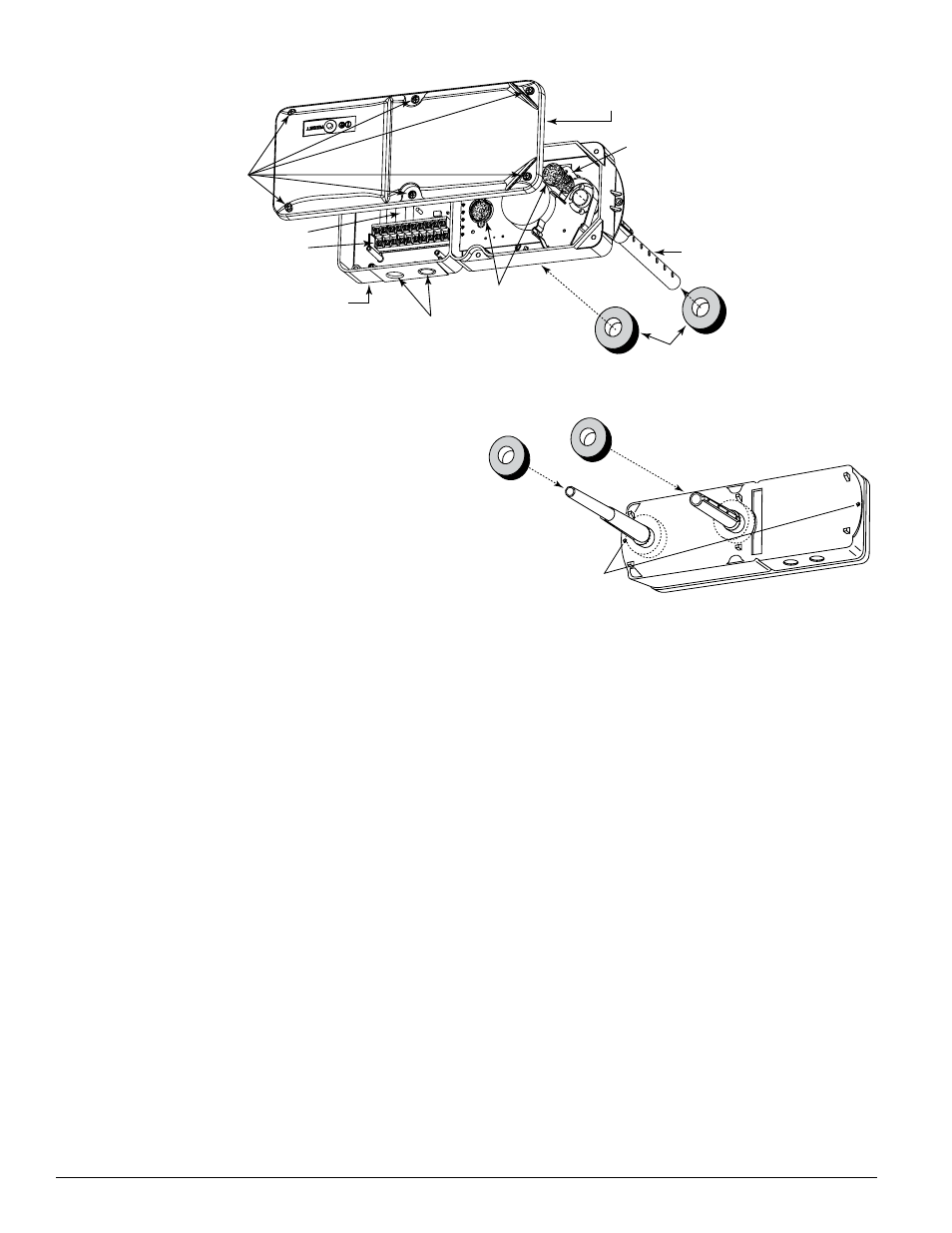
[3] Figure 1: Exploded View Of Duct Smoke Detector Components
FOAM
GASKETS
METAL
SAMPLING TUBE
SAMPLING TUBE
FILTERS
DETECTOR
COVER
DETECTOR BOARD
CONDUIT HOLES
DETECTOR
HOUSING
TERMINAL STRIP
POWER BOARD
COVER MOUNTING
SCREWS
H0174-00
H0107-01