System Sensor D4240 User Manual
Page 8
THREE-YEAR LIMITED W
ARRANTY
Sy
stem Sensor w
arr
ants its enclosed pr
oduct to be fr
ee fr
om defects in materials and
w
orkmanship under normal use and service for a period of thr
ee y
ear
s fr
om date of
manufactur
e. S
ystem Sensor mak
es no other e
xpr
ess w
arr
anty for the enclosed pr
oduct.
No agent, r
epr
esentativ
e, dealer
, or emplo
yee of the Compan
y has the authority to in
-
cr
ease or alter the obligations or limitations of this W
arr
anty
. The Compan
y’
s obligation
of this W
arr
anty shall be limited to the r
eplacement of an
y part of the pr
oduct which
is found to be defectiv
e in materials or w
orkmanship under normal use and service
during the thr
ee y
ear period commencing with the date of manufactur
e. After phoning
Sy
stem Sensor’
s toll fr
ee number 800-SENSOR2 (736-7672) for a R
eturn A
uthorization
number
, send defectiv
e units postage pr
epaid to: S
ystem Sensor
, R
eturns Department, RA
#__________,
3825
Ohio
A
venue
,
St.
Charles
,
IL
60
174.
Please
include
a
note
describing
the malfunction and suspected cause of failur
e. The Compan
y shall not be obligated to
replace units which ar
e found to be
defectiv
e because
of damage
, unr
easonable use
,
modifications
, or alter
ations occurring after the date of manufactur
e. In no case shall the
Compan
y be liable for an
y consequential or incidental damages for br
each of this or an
y
other W
arr
anty
, e
xpr
essed or implied whatsoe
ver
, e
ven if the loss or damage is caused b
y
the Compan
y’
s negligence or fault. Some states do not allo
w the e
xclusion or limitation of
incidental or consequential damages
, so the abo
ve limitation or e
xclusion ma
y not apply
to y
ou. This W
arr
anty giv
es y
ou specific legal rights
, and y
ou ma
y also ha
ve other rights
which v
ary fr
om state to state
.
Please r
efer to inser
t for the Limitations of Fir
e Alar
m Systems
Sensor
2D51
Power Board
At power-up or reset at the panel, the
sensor will take approx 35 seconds
to initialize.
Also occurs if the sensor
has been removed and restored in
the base in the sensor housing.
RED Blink every 5
seconds
Alternating
Green/amber
every 1 second
Supervisory relay
: T
erminals 3 and 14 are closed.
Alarm Relay
: T
erminals 4 and 5 are open.
Aux Relay
does not switch states:
Terminals 6 and 16 are closed,
Terminals 8 and 18 are closed
Sensor is missing during the seven
minute tamper Dela
y, if selected.
O
ff
Alternating
Green/amber
every 1 second
Supervisory relay
: T
erminals 3 and 14 are closed
Alarm Relay
: T
erminals 4 and 5 are open.
Aux Relay
does not switch states:
Terminals 6 and 16 are closed,
Terminals 8 and 18 are closed
Maintenance
Sensor 2D51 is outside it's UL
approved sensitivity limits and needs
to be cleaned or replaced.
RED Blink every 5
seconds
Amber Blink
every 5 seconds
Supervisory relay
: T
erminals 3 and 14 are closed.
Alarm Relay
: T
erminals 4 and 5 are open.
Aux Relay
does not switch states:
Terminals 6 and 16 are closed,
Terminals 8 and 18 are closed
.Unit loses Power
O
ff
O
ff
.Cover
Tamper Delay times out
Green Blink every 5
seconds
Amber solid
.Wiring Problems between the
Sensor and the Power Board
O
ff
Amber solid
.Mismatch between the number of
sensors connected and the Dip
Switch setting
1 sensor connected,2 selected
Green blink every 5
seconds on first
senso
r.
No second senso
r.
LED1 Green
blink every 5
seconds
LED2
Amber
solid
2 sensors connected,1 selected
Green blink every 5
seconds on first
senso
r.
LED's o
ff on second
sensor
LED1 Green
blink every 5
seconds
LED2
Amber
solid
Alarm
Unit detects smok
e
Solid Re
d
Solid Red
Supervisory relay
: T
erminals 3 and 14 are closed
Alarm Relay
: T
erminals 4 and 5 are closed.
Aux Relay
switches states:
Terminals 6 and 16 are open,
Terminals 8 and 18 are open
Standby
Unit has Power and it is not in
initialization,
T
rouble, Maintenance or
Alarm.
Green Blink every 5
seconds
Green Blink
every 5 seconds
Supervisory relay
: T
erminals 3 and 14 are closed
Alarm Relay
: T
erminals 4 and 5 are open.
Aux Relay
does not switch states:
Terminals 6 and 16 are closed,
Terminals 8 and 18 are closed
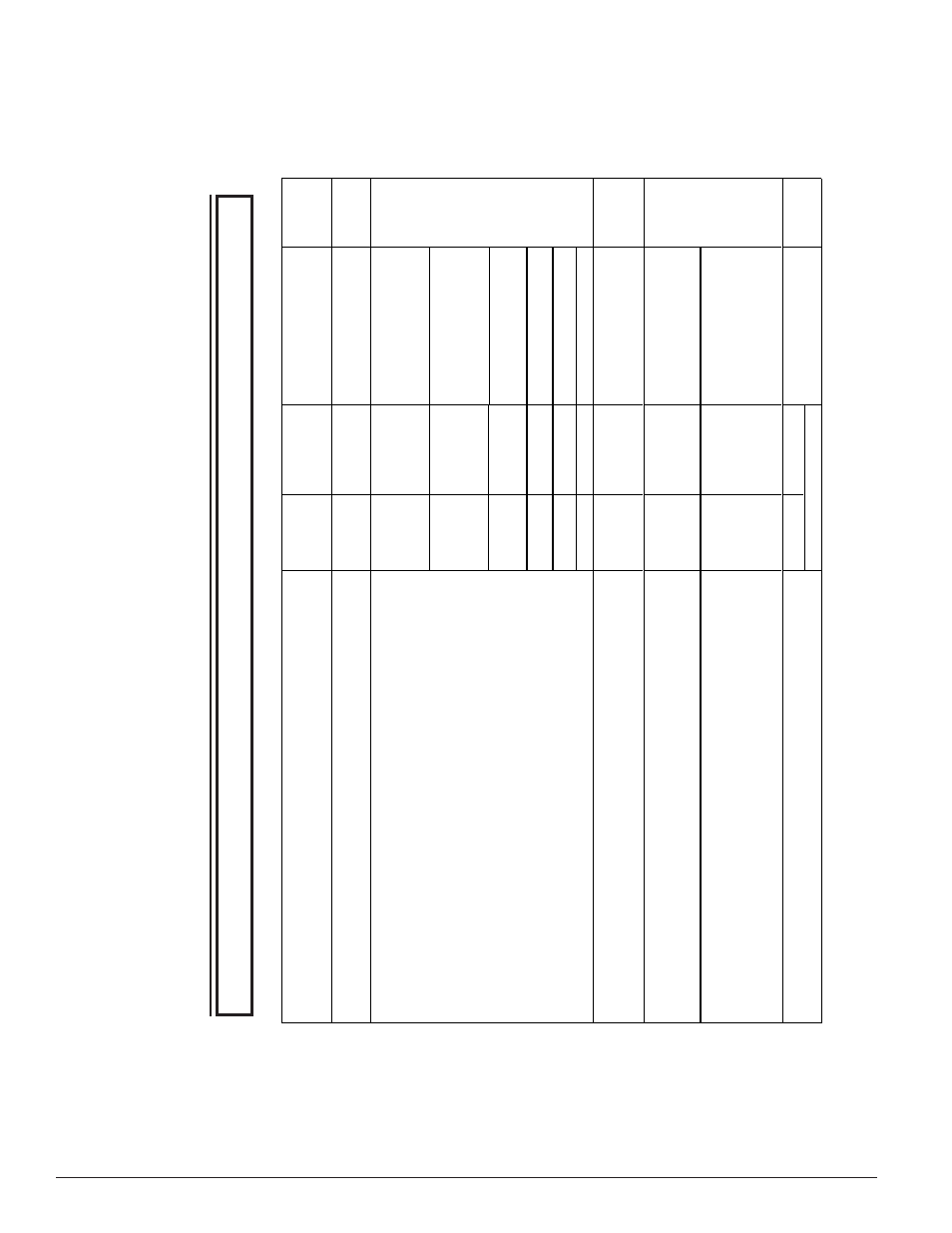
LED Status
Statu
s
Description
Status of Relays
Supervisory relay
: T
erminals 3 and 14 are open.
Alarm Relay:
Terminals 4 and 5 are open.
Aux Relay
does not switch states with no shutdown on
T
rouble selected:
Terminals 6 and 16 are closed.
Terminals 8 and 18 are closed.
Aux Relay
Switches states with shutdown on
T
rouble selected:
Terminals 6 and 16 are open,
Terminals 8 and 18 are open
Trouble
Sensor
Initialization
TABLE 3. DETECTOR ST
ATUS INDICA
TION
NO
TE: Ther
e ar
e tw
o LED’
s on the P
ow
er boar
d, each indicating the Status of the tw
o sensor
s connected.
When ther
e is only one sensor connected, LED2 will r
emain off.
NO
TE: If an
y other visual indication is noted contact S
ystem Sensor technical support at 1-800-SENSOR2.
SS-300-022
8 I56-3936-003R
©2012 System Sensor