System Sensor D4240 User Manual
Page 7
10
9
19
20
1
12
15
3
2
1
D4240
APA151/451
(GREEN LED) POWER
FIELD
INSTALLED
JUMPER
11
2
+
–
AUX OUT +
AUX OUT –
ALARM
R TEST
ACC +
ACC –
R RESET
7
18
8
17
6
16
14
3
13
5
4
SUP, NO
SUP, C
NOTE: WIRING DIAGRAM SHOWN IS FOR D4240 4-WIRE DUCT SMOKE
DETECTOR SYSTEM EQUIPPED WITHOUT A CONTROL PANEL.
NOTE: A TROUBLE CONDITION IS INDICATED
BY LOSS OF GREEN LED
COMMON
(RED LED) ALARM
AUX
AUX
ACC
ACC
AUX
AUX
ACC
ACC
(-)
(-)
(-)
(-)
(+)
(+)
(+)
(+)
RTS2/RTS2-AOS
D4240
NOTE: If polarity of Acc. (+) and Acc. (—) are reversed,
an Amber LED on sensor 2 of the duct smoke detector
power board will exist indicating a trouble condition.
SS-300-022
7 I56-3936-003R
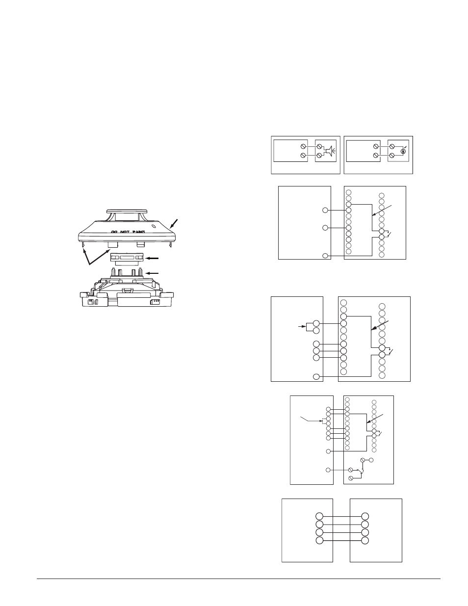
FIGURE 10. DETECTOR SENSOR EXPLODED VIEW:
SENSOR
COVER
SENSING
CHAMBER
COVER AND
SCREEN
SENSOR
CHAMBER
COVER
REMOVAL
TABS
H0584-00
10
9
19
20
1
12
15
5
4
8
3
2
6
7
D4240
SSK451
SUP. SIGNAL
POWER +
11
2
+
–
AUX OUT +
AUX OUT –
ALARM
R TEST
ACC +
ACC –
R RESET
7
18
8
17
6
16
14
3
13
5
4
SUP, NO
SUP, C
NOTE: WIRING DIAGRAM SHOWN IS FOR D4240 4-WIRE DUCT SMOKE
DETECTOR SYSTEM EQUIPPED WITHOUT A CONTROL PANEL.
POWER –
COMMON
TEMPORAL SELECT
TEST
RESET
FIELD
INSTALLED
JUMPER
FOR
TEMPORAL
PATTERN
1
19 AUX OUT +
7
ALARM SIGNAL
8
18
C
NC
NO
FIELD
INSTALLED
JUMPER
1
ALARM SIGNAL
FIGURE 14. WIRING DIAGRAM FOR D4240 TO SSK451:
FIGURE 15. WIRING DIAGRAM:
H0583-18
H0626-03
H0584-15
10
9
19
20
1
12
15
2
6
1
5
4
3
D4240
RTS451/RTS451KEY
(GREEN LED)
POWER
(RED LED)
ALARM
FIELD
INSTALLED
JUMPER
11
2
+
–
AUX OUT +
AUX OUT –
ALARM
R TEST
ACC +
ACC –
R RESET
7
18
8
17
6
16
14
3
13
5
4
SUP, NO
SUP, C
FOR RTS451KEY ONLY WITHOUT A CONTROL PANEL
FIELD
INSTALLED
JUMPERS
NOTICE: If any unitary packaged air conditioning units are run during the
drywall installation phase of any building under construction to accelerate
the drying of joint compound, the subsequent sanding of those drywall joints
and resulting dust may compromise the sensor heads in duct smoke detectors.
To avoid this condition it is recommended that the sensor heads be removed
during the construction phase.
For additional information visit www.systemsensor.com for a detailed techni-
cal bulletin.
[14] SENSOR REPLACEMENT (PART NO. 2D51)
1. Remove the sensor head by rotating counterclockwise.
2. Pull gently to remove it.
3. To replace the sensor head, align the mounting features and rotate clock-
wise into place.
[15] OPTIONAL ACCESSORIES
[15.1] RTS451/RTS151/RTS451KEY/RTS151KEY REMOTE TEST
STATION
The RTS451/RTS151/RTS451KEY/RTS151KEY Remote Test Station facilitates
test of the alarm capability of the duct smoke detector as indicated in the
RTS451/RTS151/RTS451KEY/RTS151KEY manual. The D4240 duct smoke de-
tector can be reset by the RTS451/RTS151/RTS451KEY/RTS151KEY. To install
the RTS451/RTS151/RTS451KEY/RTS151KEY, connect the device as shown in
Figure 13; wire runs must be limited to 25 ohms or less per interconnecting
wire. If a system control panel is used, the panel itself may require testing.
[15.2] SSK451 MULTI-SIGNALING ACCESSORY
The SSK451 Multi-Signaling accessory combines a sounder feature with a key ac-
tivated test and reset function. Green, amber and red LEDs provide a visual indi-
cation of power, trouble, and alarm respectively. An optional strobe (PS24LOW)
with a smoke lens can be added to conform to the codes of certain jurisdictions.
To install the SSK451, connect the device as shown in Figure 14.
H0582-24
FIGURE 11. WIRING DIAGRAMS FOR OPTIONAL ACCESSORIES:
[13.1] DETECTOR SENSOR
1. Remove the sensor to be cleaned from the system.
2. Remove the sensor cover by pulling outward on each of the four removal
tabs that hold the cover in place. See Figure 10.
3. Vacuum the screen carefully without removing it. If further cleaning is
required continue with Step 4, otherwise skip to Step 7.
4. Remove the chamber cover/screen assembly by pulling it straight out.
5. Use a vacuum cleaner or compressed air to remove dust and debris from
the sensing chamber.
6. Reinstall the chamber cover/screen assembly by sliding the edge over the
sensing chamber. Turn until it is firmly in place.
7. Replace the cover using the holes for the LEDs for alignment and then
gently pushing it until it locks into place.
8. Reinstall the detector.
[13.2] REINSTALLATION
1. Reinstall the detector in its housing.
2. Restore system power.
3. Perform Detector Check, Section 12.3.
4. Notify the proper authorities testing has been completed and the smoke
detector system is back in operation.
ALARM
AUX OUT –
15
20
(+)
(–)
ALARM
AUX OUT –
15
20
(+)
(–)
RED
MHR/MHW
(OPTIONAL) AUDIO
ALERT
D4240
DUCT DETECTOR
D4240
DUCT DETECTOR
RA400Z(OPTIONAL)
REMOTE (LED)
ANNUNCIATOR
H0554-1
FIGURE 12. WIRING DIAGRAM FOR D4240 TO APA151 OR APA451:
FIGURE 13. WIRING DIAGRAM FOR D4240 TO RTS451/RTS151/RTS-
451KEY/RTS151KEY:
15.3 RTS2/RTS2-AOS MULTI-SIGNALING ACCESSORY
The RTS2 and RTS2-AOS multi-signaling accessories are designed for use with
InnovairFlex 4-wire conventional duct smoke detectors only. The accessory
has two bicolored LEDs that indicate the sensor status of up to two connected
duct smoke detectors. The key switch on the unit can be used to select a con-
nected duct detector sensor (either sensor1 or sensor 2), and the selected sen-
sor can be tested or both sensors can be reset simultaneously using the test/
reset button. LED status indications include: Standby (green blink), Trouble
(amber), Maintenance (amber blink) and Alarm (red).
With the key switch selected, there is also the capability of obtaining a sen-
sitivity measurement of the selected sensor using the SENS-RDR sensitivity
reader (sold separately).