Figure 10. remote test station – System Sensor 6424 Projected Beam Type User Manual
Page 6
aid. If the remote power configuration is used, the remote
power source must comply with all codes and directives
of the Authority Having Jurisdiction. NOTE: The transmit-
ter should be permanently wired to the receiver (Figure
7) whenever possible to allow the alignment LEDs on the
transmitter to be used during the alignment procedure.
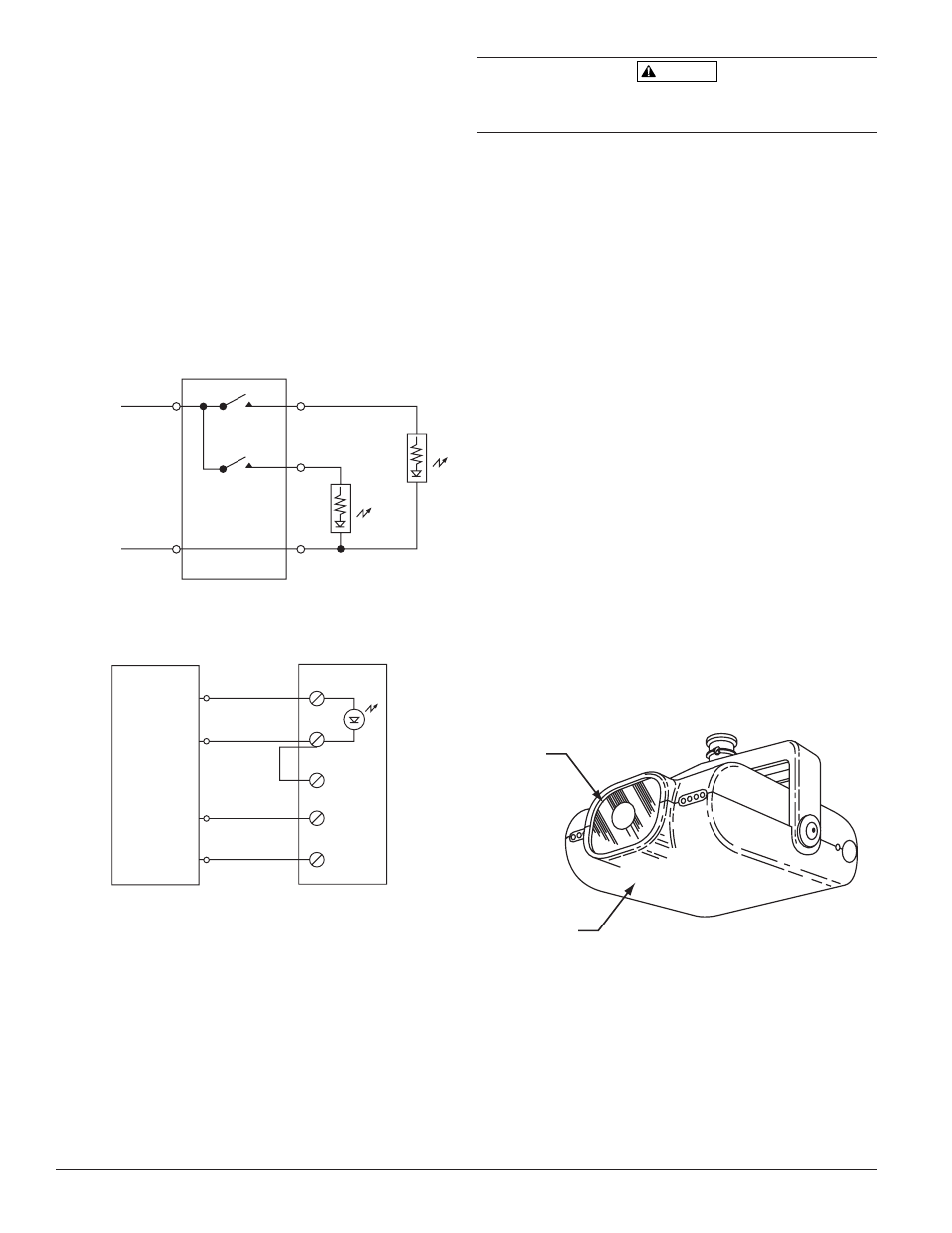
Figure 9 shows the remote outputs for trouble and alarm,
while Figure 10 shows the connection necessary for using
the remote test station (RTS451 or RTS451KEY).
NOTE: The test coil which is shipped with the RTS451 and
RTS451KEY is not used on the 6424 Beam Smoke
Detector.
Figure 9. Remote annunciators:
6424 REMOTE OUTPUTS
ORANGE
AUX (–)
TROUBLE
SIGNAL
WHITE-GREEN STRIPE
ALARM
SIGNAL
WHITE-BROWN STRIPE
POWER (+)
POWER (–)
C0543-00
Figure 10. Remote Test Station:
1
2
4
3
5
RTS451 OR RTS451KEY
REMOTE TEST STATION
6424
TEST
BLUE
RESET
YELLOW
AUX (–)
ORANGE
ALARM SIGNAL
WHITE-BROWN STRIPE
C0544-00
Installation
Reference Figures 11 through 17 for installation, align-
ment, and maintenance.
WARNING
Disconnect the power from the initiating device circuits
before installing the detectors.
1. The clear protective film and warning label on the
smoked lens of both the receiver and transmitter MUST
be removed before they can operate. To remove them,
grasp a free corner of the clear protective film and pull
so that both the film and the warning label are peeled
from the smoked glass lens.
2. Mount brackets and connect cables properly as detailed
above.
3. Insert the flange of the detector mounting bracket into
the keyed hole of the wall or ceiling mounting bracket.
Slide the detector forward into position. The detector
should now hang from the bracket.
4. Insert the correct screw and washer combination (either
wall or ceiling mount) through the slot and into the hole
of the mounting bracket flange. Tighten the screw until
almost snug. The detector should still turn easily in both
directions.
5. Open the sliding access door on the back of the unit.
6. Plug cable connector into slot in metal barrier, observing
proper orientation (see Figures 14 and 15).
7. Repeat for the other unit.
8. IMPORTANT: If the detector spacing is between 30 and
60 feet, the additional filter (included) must be attached
to the receiver lens. Peel the protective backing off the
filter and install as shown in Figure 11.
Figure 11. Additional filter required for installations
with 30 to 60 Ft. spacing only:
Additional
Lens
Receiver
C0545-00
Alignment
Figure 16. Front View Transmitter and Receiver
D400-18-00
6
I56-494-13R
PRINTED IN MEXICO