Sensitivity in %/ft vs distance – System Sensor 6424 Projected Beam Type User Manual
Page 10
indicate alignment mode, but the trouble relay will
not activate. If the receiver is left in the alignment
mode for more than an hour, the trouble relay will
activate.
9) Point the receiver directly at the transmitter.
B) RECEIVER ALIGNMENT PROCEDURE:
1) Align the receiver by slowly moving it back and forth,
and up and down until all four LEDs light. (NOTE: If
it is impossible to get all four LEDs to light, the trans-
mitter may need to be adjusted. Go to the transmitter
and align it so that all four LEDs light, and then go
back to the receiver and continue with step 2.)
2) Adjust the alignment adjust pot until only three align-
ment LEDs are lit.
3) Further align the receiver by slowly moving it back
and forth, and up and down, trying to get all four
LEDs to light.
REPEAT STEPS 2 AND 3 UNTIL IT IS IMPOSSIBLE TO
GET MORE THAN THREE LEDs TO LIGHT. (NOTE:
If steps 2 and 3 are carefully executed, it should take
two to five tries to align the receiver.)
4) Carefully tighten the horizontal adjustment screws
first and then the two vertical adjustment screws on
the receiver bracket, making sure all three alignment
LEDs remain lit.
C) TRANSMITTER ALIGNMENT PROCEDURE:
1) Slowly move the transmitter back and forth, and up
and down, trying to get all four LEDs to light.
2) If four LEDs light, adjust the alignment adjust pot on
the receiver until only three alignment LEDs are on.
REPEAT STEPS 1 AND 2 UNTIL IT IS IMPOSSIBLE TO
GET MORE THAN THREE LEDs TO LIGHT. (NOTE:
If steps 1 and 2 are carefully executed, it should take
between two and five tries to achieve this.)
3) When it is impossible to get more than three LEDs
to light, carefully tighten the horizontal adjustment
screws and then the vertical adjustment screws on the
transmitter bracket, making sure all three alignment
LEDs stay lit.
4) Slide the alignment switch on the transmitter to the
NORMAL MODE (N) position (see figure 15) and
disconnect any temporary wiring. Carefully close the
door on the transmitter and go to the receiver.
5) Verify that three alignment LEDs are lit and switch
back to NORMAL MODE (N) at the receiver. It is
important that three alignment LEDs are on (not
four) when leaving alignment mode. This ensures
that the amplifier is not saturated with signal and
will be capable of detecting smoke within its sensitiv-
ity limits. Wait at least one minute before continuing.
Do not block or disturb the beam while it is calibrat-
ing. Any interference could cause a trouble signal. If
there is a trouble signal during this period, switch the
receiver back to ALIGN MODE to make sure that only
three LEDs are lit. Switch back to NORMAL MODE
and wait again. If three alignment LEDs are not on,
repeat the transmitter alignment procedure.
6) When the detector has completed it’s self-calibration,
the green (normal) operation LED will flash every two
or three seconds. Alignment is now complete.
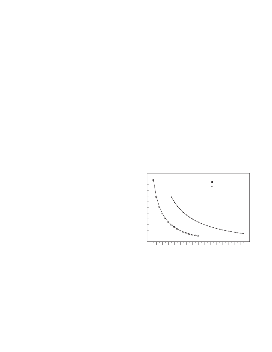
Sensitivity
Total obscuration can be converted to percent per foot,
assuming uniform smoke density for the entire length of
the beam. The chart below converts total obscuration to
percent per foot at both 30% and 55% sensitivity settings.
SENSITIVITY IN %/FT VS DISTANCE
ASSUMING UNIFORM SMOKE DISTRIBUTION
DISTANCE (FEET)
OBSCURA
TION (%/FT)
30
40
50
60
70
80
90
100
110
120
130
140
150
160
170
180
190
200
210
220
230
240
250
260
270
280
290
300
310
320
330
1.3
1.2
1.1
1
0.9
0.8
0.7
0.6
0.5
0.4
0.3
0.2
0.1
= 30% Sensitivity Setting
= 55% Sensitivity Setting
C0552-00
Sensitivity Testing
NOTE: Before testing, notify the proper authorities that the
smoke detector system is undergoing maintenance,
and therefore the system will be temporarily out
of service. Disable the zone or system undergoing
maintenance to prevent unwanted alarms.
Detectors must be tested after installation and following
periodic maintenance. The sensitivity of the 6424 may be
tested as follows:
D400-18-00
10
I56-494-13R
PRINTED IN MEXICO