System Sensor SPSW-ALERT User Manual
Page 2
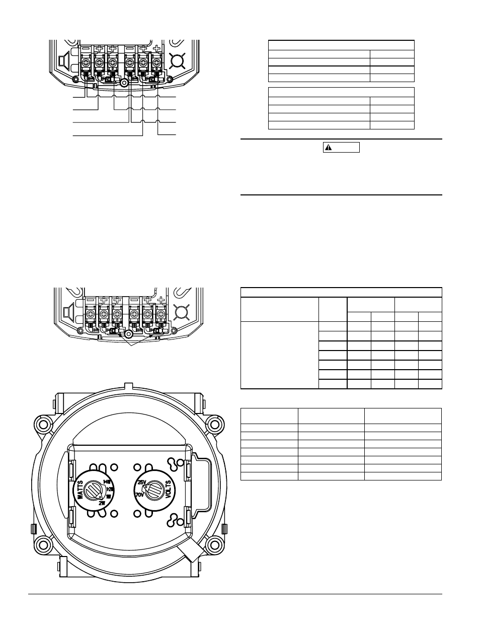
TabLe 1. soUnd LeveLs for eaCh Transformer poWer Tap:
UL Reverberant (dBA @ 10 ft.)
2W
85
1W
82
1
/
2
W
79
1
/
4
W
76
CAUTION
Signal levels exceeding 130% rated signal voltage can damage the speaker.
Consequently, an incorrect tap connection may cause speaker damage. This
means that if a 25V tap is selected when a 70.7V amplifier is being used,
speaker damage may result. Therefore, be sure to select the proper taps for the
amplifier voltage/input power level combination being used.
CandeLa seLeCTion
Adjust the slide switch on the rear of the product to position the desired can-
dela setting in the small window on the front of the unit. For amber lensed
strobes used for full profile measurement, listed candela ratings must be re-
duced in accordance with Table 3. Use Table 2 to determine the current draw
for each candela setting.
NOTE: SpectrAlert products set at 15 and 15/75 candela automatically work
on either 12V or 24V power supplies. The products are not listed for 12V op-
erating voltages when set to any other candela settings.
TabLe 2. sTrobe CUrrenT draW measUremenTs:
Strobe Current Draw(mA)
Candela
8-17.5 Volts
16-33 Volts
DC
FWR
DC
FWR
Standard Candela Range
15
123
128
66
71
15/75
142
148
77
81
30
NA
NA
94
96
75
NA
NA
158
153
95
NA
NA
181
176
110
NA
NA
202
195
115
NA
NA
210
205
TabLe 3. CandeLa deraTinG:
Cd Switch Setting
On-Axis Rating
(UL 1638)
Equivalent Cd Rating for
UL1971 Profile
15
15
12
15/75
15/75
15/75
30
30
24
75
75
60
95
95
75
110
110
85
115
115
90
NOTE: UL1971 is not applicable to mass notification devices, but these readings
were obtained using the measurement procedure specified under UL1971.
moUnTinG
1. Attach mounting plate to junction box as shown in Figure 4. The mounting
plate is compatible 4˝ x 4˝ x 2
1
/
8
˝ junction boxes. If using a back box skirt or
trim ring, attach the mounting plate to the skirt or trim ring and then attach
the entire assembly to the junction box (see Figures 4 and 5).
2. Connect field wiring to terminals, as shown in Figure 1.
3. If the product is not to be installed at this point, use the paint cover to
prevent contamination of the mounting plate.
4. To attach product to mounting plate, remove the paint cover, then hook
tabs on the product housing into the grooves on mounting plate.
fiGUre 1. WirinG diaGram:
INPUT FROM
AMPLIFIER
INPUT FROM
POWER
SUPPLY
OUTPUT TO
NEXT SPEAKER
OR EOL
OUTPUT TO
NEXT STROBE
OR EOL
(–)
(+)
(–)
(+)
(–)
(+)
(–)
(+)
A0388-00
eLeCTriCaL WirinG
1. Connect the speaker as shown in Figure 1.
NOTE: Do not loop electrical wiring under terminal screws. Wires con-
necting the device to the control panel must be broken at the device
terminal connection in order to maintain electrical supervision.
2. There are two rotary switches on the back of the product The first switch
is used to select either 25 or 70.7 volts input for the speaker portion. The
second switch is used to select the input power of
1
/
4
,
1
/
2
, 1 or 2 watts.
See diagram.
shorTinG sprinG
NOTE: Shorting springs are provided between terminals 2 and 3 and between
terminals 5 and 6 of the mounting plate to enable wiring checks after the
system has been wired, but prior to installation of the final product. These
springs will automatically disengage when the product is installed, to enable
supervision of the final system.
fiGUre 2. shorTinG sprinG
SHORTING SPRINGS
A0391-00
fiGUre 3. speaker WaTTaGe and voLTaGe seTTinGs:
C0419-00
SS-140-002
2
I56-3935-001R
UL Anechoic (dBA @ 10 ft.)
2W
88
1W
86
1
/
2
W
83
1
/
4
W
80