Figure 2, Figure 3 – System Sensor PF24V Exitpoint User Manual
Page 3
D690-06-00
3 I56-2961-001R
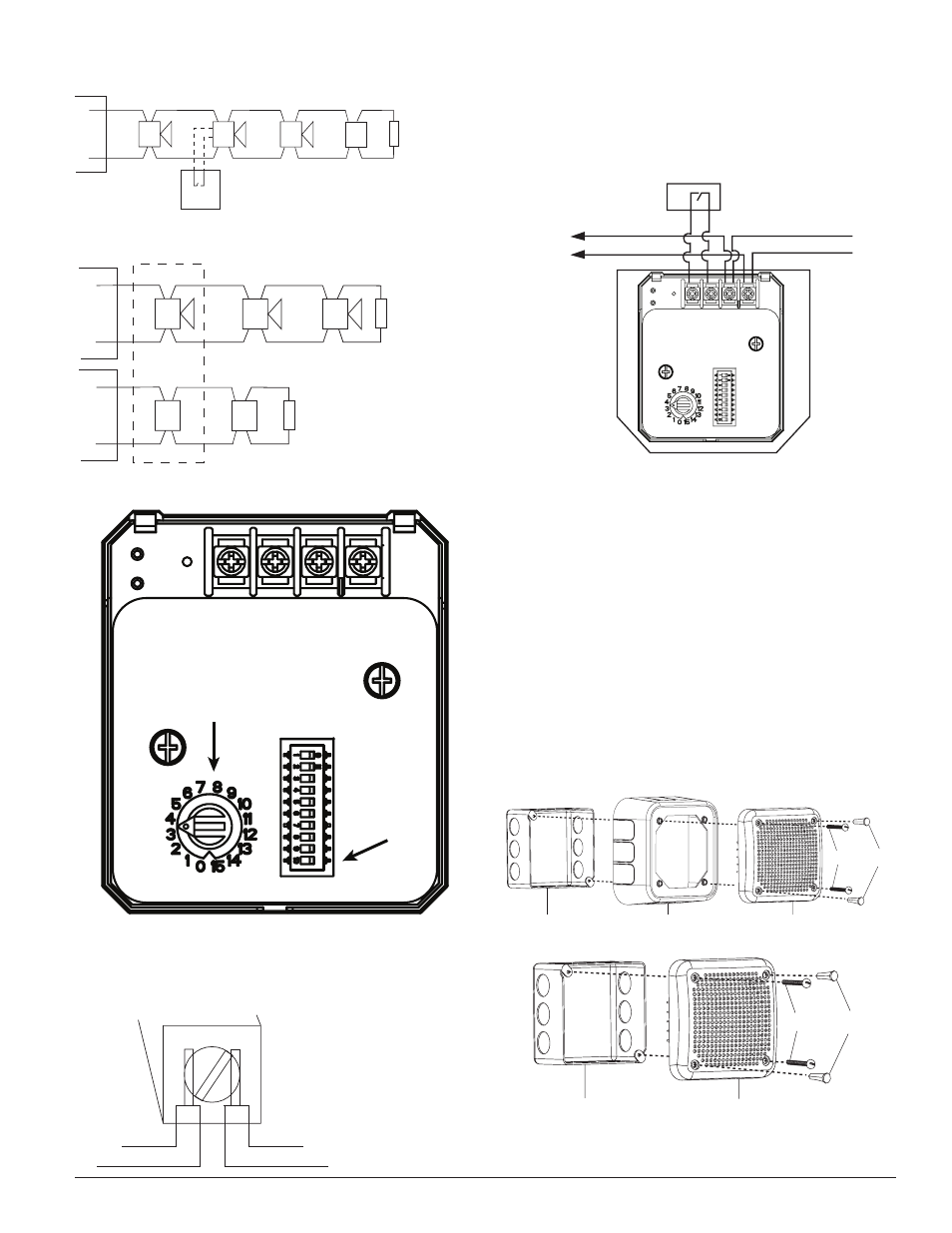
FIGURE 1.
TWO WIRE SYSTEM
ANY MIX OF MODELS
OPTIONAL DISABLE CONTACT
NOTE: SWITCH POSITION 4 SETS
THIS INPUT TO EITHER
ACTIVE OPEN OR ACTIVE CLOSED.
HORN
(+)
(–)
(+)
(–)
E
O
L
(+)
(–)
(+)
(–)
(+)
(–)
HORN/STROBE
DIRECTIONAL
SOUNDER
STROBE ONLY
A0338-00
FIGURE 2.
FOUR WIRE SYSTEM:
ANY MIX OF HORNS
AND SOUNDERS OR
HORN/STROBES
HORN/STROBE
(+)
(–)
(+)
(–)
E
O
L
(+)
(–)
(+)
(–)
HORN
DIRECTIONAL
SOUNDER
FOUR WIRE SYSTEM:
ANY MIX OF STROBES
AND HORN/STROBES
STROBE
POWER
SUPPLY
SOUNDER
POWER
SUPPLY
(+)
(–)
(+)
(–)
E
O
L
(+)
(–)
STROBE
A0344-00
FIGURE 3.
ROTARY SWITCH
USED FOR
LANGUAGE
SELECTION
DIP SWITCHES
USED FOR SPEED
SETTINGS, POWER
SELECTION,
ADDITIONAL TONES,
AND DISABLE
FUNCTION
NOTE: DO NOT loop electrical wiring under terminal screws. Wires connect-
ing the device to the control panel must be broken at the device terminal con-
nection in order to maintain electrical supervision. See Figure 4.
FIGURE 4.
BREAK WIRE AS SHOWN FOR
SUPERVISION OF CONNECTION.
DO NOT ALLOW STRIPPED WIRE
LEADS TO EXTEND BEYOND SWITCH
HOUSING. DO NOT LOOP WIRES.
A0337-00
The sounder has a set of input terminals to provide additional control of the
sound output of the directional sounder. These terminals can be connected to
the dry relay contacts of control devices such as heat sensors or control mod-
ules. When the input is active it will disable the sound output of the Sounder.
Connect the disable function as shown in Figure 5. Refer to Table 3 for func-
tion switch settings.
FIGURE 5.
– VDC
TO NEXT DEVICE
OR EOL
OPTIONAL DISABLE CONTACT
+ VDC
MECHANICAL
Two screws are included for attaching the sounder to the electrical junction
box.
NOTE: If surface mounting is required, an extension ring will be necessary to
give proper depth for mounting the sounder. The minimum depth required,
in the backbox/extension ring combination, is 2¼˝. Any combination of 4˝ ×
4˝ backbox and 4˝ × 4˝ extension ring that gives an interior depth of at least
2¼˝ may be used.
MOUNTING
See Figure 6. The sounder can be flush mounted on a 4˝ Ч 4˝ Ч 2¼˝ back
box, as follows:
A. Use the two 8-32 × 1¾˝ screws (provided) to attach the Sounder to
the back box.
B. Plug the remaining two holes that will not be used for attachment
with the plugs provided.
FIGURE 6.
4" x 4" x 2-1/4"
BACKBOX
PF24V
8-32
SCREWS
FILL
PLUGS
Skirt, BBS-SP201W
A0359-00
C0928-00
A0929-00
4" x 4" x 2-1/4"
BACKBOX
PF24V
8-32
SCREWS
FILL
PLUGS
A0176-05