System Sensor PF24V Exitpoint User Manual
Page 2
D690-06-00
2 I56-2961-001R
INSTALLATION
Consult the ExitPoint Applications Guide (A05-1048-XXX) for information re-
garding the appropriate mounting locations of directional sounders.
DIP SWITCHES FOR SPEED SETTINGS
DIP switch positions 7-10 are used to select the speed setting of the sounder.
Switch 10 is the fastest speed and is used to mark perimeter exits and stair-
wells. The remaining settings are used for egress guidance to the perimeter ex-
its. The egress route would begin with the slow setting (switch 7) and follow
medium fast (switch 9) and medium slow (switch 8) and finally the fast set-
ting (switch 10). If more than one switch is selected the sounder will default
to the fastest setting.
DIP SWITCH SETTINGS FOR ALERTING MESSAGES
DIP switch positions 5 and 6 are used to select additional tone pulses that
can be inserted between bursts of directional sound pulses. These messages
are used to give building occupants instructions. There are four messaging
options to choose from. “Stairs Up” (Switch 5 off, Switch 6 on) will notify oc-
cupants that they are approaching a stairwell and will need to go up. “Stairs
Down” (Switch 5 on, Switch 6 off) will notify occupants that they are ap-
proaching a stairwell and will need to go down. “Area of Refuge” (Switches
5 & 6 on) alerts people who need to find these areas of refuge in a building.
“Exit Here” (Switches 5 & 6 off ) notifies occupants that they have reached
the perimeter exit.
TABLE 2. ADDITIONAL TONE SELECTION GUIDE:
DIP Switch
Position 5
Setting
DIP Switch
Position 6
Setting
Sound Output
on
on
Area of Refuge
on
off
Stairs DOWN
off
on
Stairs UP
off
off
Exit Here
DIP switch setting 4 enables a directional sound device to become disabled
when used in conjunction with devices with dry contacts such as heat sen-
sors or control modules. The sounder has a set of input terminals that can be
configured for an “active open” or “active closed” state. When the switch is in
the “on” position, the sounder is “on” when the disable connection is closed.
When the switch is in the “off” position, the sounder is “on” when the disable
connection is open. See Table 3 for operation modes.
TABLE 3. ENABLE/DISABLE FUNCTION LOGIC TABLE:
DIP Switch
Position 4
Setting
Wiring
Terminals
3 & 4
Sound
Output
on
open
disabled
on
closed
enabled
off
open
enabled
off
closed
disabled
There are five different power settings for the sound output pressure. Switch
settings 1, 2, and 3 set the power setting for the sounder. Switch 1 selects the
Med-High setting, switch 2 selects the Medium setting, switch 3 selects the
Med-Low setting. If all three switches are “off” this selects the High setting
and if all three switches are “on” this selects the Low setting.
Directional Characteristics are as follows:
-3dBA angles -40, 130 horizontal and vertical
-6dBA angles -15, 160 horizontal and vertical
TABLE 4. POWER SETTING GUIDE:
DIP Switch
Position 1
Setting
DIP Switch
Position 2
Setting
DIP Switch
Position 3
Setting
Power
Setting
off
off
off
High
on
off
off
Med-High
off
on
off
Med
off
off
on
Med-Low
on
on
on
Low
NOTE 1: Any other combinations of switch setting for positions 1, 2, and 3 are
invalid and should not be used.
Consult the ExitPoint Applications Guide for information regarding the appro-
priate power, speed, and additional tone selections.
LANGUAGE SELECTION
Language selection and audible tones are selected via the rotary code switch.
If no language is selected, the device is capable of playing audible tones to
alert occupants of stairs up, stairs down, and area of refuge. Refer to Table 5
language selection and Figure 3 for diagram.
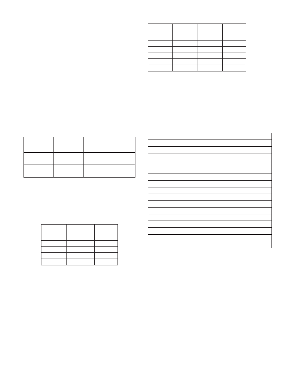
TABLE 5. LANGUAGE/AUDIBLE TONE SELECTION GUIDE:
Rotary Switch Selection
Tone/Language
0
Audible tone/sweep
1
English
2
Spanish
3
French
4
English/Spanish
5
English/French
6
Korean
7
Cantonese
8
Mandarin
9
English/Cantonese
10
English/Mandarin
11
Cantonese/Mandarin
12
English/Korean
13
English/Portuguese
14
English/Russian
15
English/Polish
ELECTRICAL
Connect the Sounder as shown in Figure 1 for 2-wire applications. Connect
the sounder as shown in Figure 2 for 4-wire applications.
4-wire notification appliance circuits are circuits that use a separate power
supply and pair of wires for sounder and strobe circuits. Some types of no-
tification circuits may provide coded signals to the sounders by pulsing the
power supply on and off in specific patterns such as the temporal 3 evacuation
signal. The directional sounders should not be connected to 4-wire sounder
circuit power supplies where coded signals are used to pulse the sounders. Di-
rectional sounders may be used in conjunction with sync modules such as the
System Sensor MDL3, MDL3A or synchronizable power supplies. The sounder
is compatible with synchronizable power supplies using any of the following
synchronization protocols; System Sensor, Wheelock, Gentex, and Faraday.
Note: In an effort to minimize interference of tones it is highly recommended
that you do not place horn and/or horn strobe devices in close proximity
of the directional sounder. In addition, it is recommended that if you have
a voice evacuation system, you alternate the directional sounders and your
voice messages.
All wiring must be installed in compliance with the National Electrical Code
(NEC), Canadian Electrical Code and applicable local codes as well as special
requirements of the authority having jurisdiction.