System Sensor Dual Strobe Expander Plates User Manual
Page 3
SS-120-005
3 I56-3829-001R
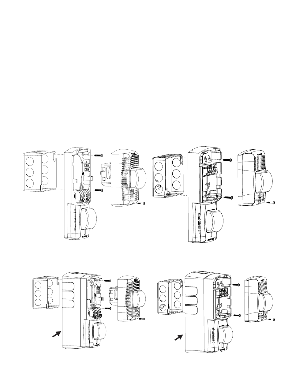
FiGUre 5. Sep-SpSW Speaker STrobe expander pLaTe
For FLUSh moUnT appLiCaTionS:
FiGUre 6. Sep-SpSW Speaker STrobe expander pLaTe
For SUrFaCe moUnT appLiCaTionS:
FiGUre 7: Sep-SW STrobe expander pLaTe
For FLUSh moUnT appLiCaTionS:
FiGUre 8. Sep-SW STrobe expander pLaTe
For SUrFaCe moUnT appLiCaTionS:
SPSEP-BBSW
SPEAKER STROBE
BACK BOX SKIRT
SEP-BBSW
STROBE BACK
BOX SKIRT
A0449-00
A0450-00
A0451-00
A0452-00
moUnTinG The Sep-SW STrobe expander pLaTe
1. Attach strobe expander plate to junction box as shown in Figure 7. The
strobe expander plate is compatible with 4-inch square, double gang,
single gang and 4-inch octagonal junction boxes. If using a back box
skirt, attach the strobe expander plate to the skirt and then attach the
entire assembly to the junction box (see Figure 8). The back box skirt is
only compatible with a 4˝x4˝x2
1
/
8
˝ junction box.
2. Connect field wiring to terminals, as shown in Figure 3.
3. If the strobe device is not to be installed at this point, use position the
paint cover onto the mounting plate to prevent contamination of the field
wiring terminals.
4. To attach strobe device to the strobe expander plate, remove the paint
cover, then hook tabs on the product housing into the grooves on strobe
expander plate.
5. Swing the strobe device into position to engage the pins on the device
with the terminals on the strobe expander plate. Make sure that the tabs
on the back of the product housing fully engage with the strobe expander
plate.
6. Secure the device by tightening the single mounting screw in the front of
the device housing. For tamper resistance, the standard captive mounting
screw may be replaced with the enclosed Torx screw.