Shorting spring – System Sensor Dual Strobe Expander Plates User Manual
Page 2
(+)
(–)
(+)
(–)
(+)
(–)
(+)
(–)
Input from
FACP or Prior
Fire Strobe
Input from Power
Supply for Alert Strobe
or Prior Alert Strobe
Output to Next
Fire Strobe or EoL
Output to Next
Alert Strobe or EoL
SS-120-005
2 I56-3829-001R
moUnTinG The Sep-SpSW Speaker STrobe expander pLaTe
1. Attach the speaker strobe expander plate to the junction box as shown in
Figure 5. The speaker strobe expander plate is compatible with a 4˝ x 4˝
x 2
1
/
8
˝ junction box. If using a back box skirt, attach the speaker strobe
expander plate to the back box skirt and then attach the entire assembly
to the junction box (see figure 6).
2. Connect the field wiring to the terminals, as shown in Figure 1.
3. If the speaker strobe device is not to be installed at this point, use the
paint cover to prevent contamination of the speaker strobe expander
plate.
4. To attach the speaker strobe device to the speaker strobe expander plate,
remove the paint cover, then hook the tabs on the product housing into
the grooves on the strobe plate.
5. Swing the speaker strobe device into position to engage the pins on the
device with the terminals on the speaker strobe expander plate. Make
sure that the tabs on the back of the device housing fully engage with the
expander plate.
6. Secure the speaker strobe device by tightening the single mounting
screw in the front of the speaker strobe housing. For tamper resistance,
the standard captive mounting screw may be replaced with the enclosed
Torx screw.
TabLe 1. STrobe CUrrenT draW ( ) For Sep-SW, Sep-SpSW:
ma
A0447-00
A0448-00
SHORTING SPRING
FiGUre 3. WirinG The Sep-SW: STrobe expander pLaTe,
STandard CandeLa, WhiTe:
(+)
(–)
(+)
(–)
(+)
(–)
(+)
(–)
Input from
Amplifier or
Prior Speaker
Input from
FACP or Prior
Fire Strobe
Output to Next
Speaker or EoL
Output to Next
Fire Strobe or EoL
(+)
(–)
(+)
(–)
Input from Power
Supply for Alert Strobe
or Prior Alert Strobe
Output to Next Alert
Strobe or EoL
A0446-00
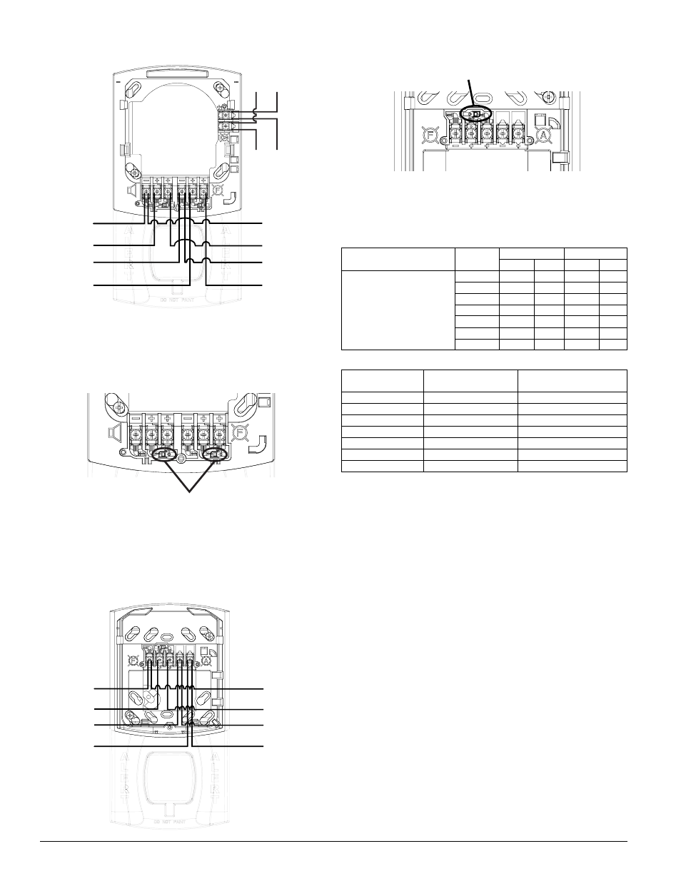
Shorting Spring
FiGUre 2. ShorTinG SprinG on Sep-SpSW Speaker STrobe
expander pLaTe, STandard CandeLa,WhiTe:
FiGUre 4. ShorTinG SprinG on Sep-SW STrobe expander
pLaTe, STandard CandeLa, WhiTe:
A0445-00
FiGUre 1. WirinG Sep-SpSW Speaker STrobe expander pLaTe,
STandard CandeLa,WhiTe:
Candela
8–17.5 Volts
16–33 Volts
DC
FWR
DC
FWR
Standard Candela Range
15
123
128
66
71
15/75
142
148
77
81
30
NA
NA
94
96
75
NA
NA
158
153
95
NA
NA
181
176
110
NA
NA
202
195
115
NA
NA
210
205
NOTE: The total number of strobes on a single NAC must not exceed 40 for
24 volt applications or 12 for 12 volt applications. Loop resistance on a single
NAC should not exceed 120 ohms for 24 volt and 30 ohms for 12 volt systems.
NOTE: A shorting spring is provided between terminals 2 and 3 of the mount-
ing plate to enable wiring checks after the system has been wired, but prior
to installation of the final product. This spring will automatically disengage
when the product is installed, to enable supervision of the final system.
TabLe 2: CandeLa deraTinG For amber LenS STrobe
Cd Switch Setting
On-Axis Rating
(UL 1638)
Equivalent Cd Rating for
Wall profile (UL 1971)
15
15
12
15/75
15/75
15/75
30
30
24
75
75
60
95
95
75
110
110
85
115
115
90
NOTE: UL1971 is not applicable to mass notification devices, but these read-
ings were obtained using the measurement procedure specified under UL1971.
IMPORTANT: For more information on current draw, light output and sound
output data, reference Speaker Strobe installation manual I56-3935 and Strobe
only installation manual I56-2769.
NOTE: Shorting springs are provided between terminals 2 and 3 and terminals
5 and 6 of the mounting plate to enable wiring checks after the system has
been wired, but prior to installation of the final product. These springs will
automatically disengage when the product is installed, to enable supervision
of the final system.