Caution, Danger, Warning – Superwinch S9000 - 4,082 kgs/12V (1916, 1918) User Manual
Page 5
NOTES:
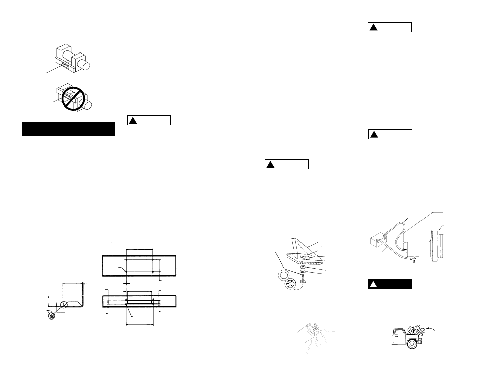
1. All dimensions are in inches
(millimeters).
2. Winch is mounted with 3/8-16
(M 10) hardware. Using 1/4
inch (6.4) thick steel baseplate,
bolt length to be 1 inch (25.4).
Bolts to be SAE Grade 8
(ISO 10.9) or stronger.
3. Use only square nuts in casting
for mounting. (See Figure 8.)
MOUNTING DIMENSIONS
10 (254.0)
4 1/2
(114.3)
1 13/32 (35.7)
13/32 (10.3)
Dia. Holes
(4) Places
Alternate Construction of
Structural Reinforcement
Weld
4 1/8 (104.8)
7 1/2 (190.5)
1/4 (6.4)
1 3/8 (34.9)
1/2 (12.7)
Max. Rad.
1 9/16 (39.7)
5/32 (4.0)
19/32
(15.1)
7/8
(22.2)
13/32 (10.3) Dia.
10 5/16 (261.9)
3/16 (4.8)
Opening
1 3/16 (30.2)
9 (228.6) Opening
9
29. Always operate your winch in
an underwound orientation
only.
MOUNTING YOUR WINCH
Superwinch mounting (fitting) fits
are available for most popular vehi-
cles. If you can‘t locate a kit locally,
contact Superwinch at the address
listed on the front of this manual
for the name of a Superwinch deal-
er near you.
Detailed mounting instructions are
provided with each mounting kit.
Read and install carefully to ensure
proper winch alignment and trou-
ble-free operation.
If a Superwinch mounting plate is
not used, refer to Figure 7 for a
guide to construct a mounting system.
Note: This winch MUST be mount-
ed with the wire rope in the under-
wind direction.
Improper
mounting
could damage your winch, void
the warranty, and cause personal
injury.
MINIMUM ELECTRICAL
REQUIREMENTS
For 12 Volt winches, a 60 amp alter-
nator and battery with 440 cold-
cranking amperes capacity are the
minimum recommended power
sources. If the winch is in heavy use,
an auxiliary battery and heavy duty
alternator with battery isolator are
recommended.
TOOLS REQUIRED
Open End Wrenches (Spanners):
*(2) 3/8", *(2) 1/2", *(2) 7/16",
*(2) 9/16"
(1) 1/4 inch Hex socket wrench or
straight blade screwdriver
*Adjustable (Crescent) Wrenches may be substituted.
1. Install mounting kit or structural
support for winch.
2. Attach the long black color-coded
wire to the motor case (see
Figure 10). Mount the winch to
the mounting kit base plate or
to the mount that you designed
(see Figure 7).
The 3/8-16 mounting bolts sup-
plied are the correct length for
use with a 1/4" thick Superwinch
mounting plate.
The end of the
mounting bolts
must not contact the opposite side
of the support casting’s mounting
pocket (see Figure 8).
Such contact could lead to a damaged
casting, catastrophic failure of the
winch and void the warranty. Adjust
bolt length accordingly if a thicker
plate is used. The bolt threads must
engage all the nut threads.
Always place the square nuts (pro-
vided) in the casting pockets when
mounting your winch.
Do not sub-
stitute any
strength grade weaker than SAE
Grade 8 (ISO 10.9). Grade marking
is found on the bolt head and is
pictured in Figure 8.
3. If you choose to locate the winch
at a greater distance than the
wires provided will permit, it may
be necessary to purchase a larger
gauge wire to get the best per-
formance from your winch. If the
total length of additional wire to
be added to the system exceeds
10 ft. (3m), use a larger wire
gauge size.
When attaching
wires to the
motor terminals and solenoids
(relays), hold the inner nut when
tightening the outer nut. Do not
allow the motor terminals to rotate
causing internal wire breakage or
part misalignment. Be especially
careful in preventing the solenoid
(relay) terminals from rotating. Any
rotation can damage the solenoid
(see Figure 9).
4. Disconnect the vehicle battery
leads.
Automobile bat-
teries contain
gasses which are flammable and
explosive. Wear eye protection
during installation and remove
all metal jewelry. Do not lean over
battery while making connections.
(Fig. 11).
I N S T A L L A T I O N
Figure 10
Support Casting
Mounting Pocket
Square Nut
Flat Washer
Lock Washer
(Must not
touch)
Grade 8 Bolt
Mounting
Plate
10.9
Figure 9
8
Figure 8
Figure 7
Red
Black
CAUTION
!
CAUTION
!
DANGER
!
WARNING
!
Be Prepared
Figure 11
Fig 2
Overwind
Underwind
CAUTION
!