Ir application diagrams, Using in-room ir receiver and remote, Programmed control system – Staub Electronics EA-MINI-2D-35 EPISODE - 2 CHANNEL 35 WATTS DIGITAL MINI-AMPLIFIER User Manual
Page 14: Ir receiver ir flasher switch 1 down, Ir flasher, Automation controller 3.5mm mono cable switch 1 up
EA-MINI-XD-35 Installation Manual
Pg. 14
© 2013 Episode
®
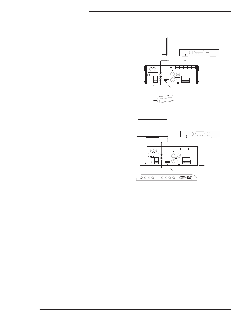
11.3. IR Application Diagrams
To control the amplifier with an in-room IR remote (commands
transmit directly from the remote):
1. Set dip switch 1 to the DOWN position.
2. Connect the IR Receiver to the IR In port.
3. Position the receiver so that commands are received
reliably.
4. Control additional equipment by attaching an IR flasher
to the IR Out port.
To control the amplifier with a control system:
1. Set dip switch 1 to the UP position.
2. Connect a 3.5mm mono mini cable from the flasher
output of the controller to the IR In port on the amplifier.
3. Program the control system using the IR control protocol.
4. Control additional equipment by attaching an IR flasher
to the IR Out port.
All IR commands may be found in the EA-MINI-XD-35
Control Protocol which may be downloaded from the
amplifier product page at www.snapav.com.
11.3.1. Using In-Room IR Receiver and Remote
11.3.2. Programmed Control System
R+ R- L+ L-
DIGITAL IN
SUB OUT
ANALOG IN
RIGHT
1 2 3 4 5
IR IN
IR OUT
+5V GND
RESET
SPEAKER OUTPUTS
STATUS
1
2
LEFT
SWITCHES
100-240V~50/60Hz 1.6A
UP
1
2
3
4
5
CONTROL
DOWN
IR
RECEIVER
RUN
LEARN
MONO
STEREO
FULL
HP 60Hz
IN 1
IN 2
SWITCH POSITION
256
IR Receiver
IR Flasher
Switch 1 DOWN
R+ R- L+ L-
DIGITAL IN
SUB OUT
ANALOG IN
RIGHT
1 2 3 4 5
IR IN
IR OUT
+5V GND
RESET
SPEAKER OUTPUTS
STATUS
1
2
LEFT
SWITCHES
100-240V~50/60Hz 1.6A
UP
1
2
3
4
5
CONTROL
DOWN
IR
RECEIVER
RUN
LEARN
MONO
STEREO
FULL
HP 60Hz
IN 1
IN 2
SWITCH POSITION
256
IR Flasher
IR Outputs
RS232
IR Inputs
Automation Controller
3.5mm Mono Cable
Switch 1 UP