Rear panel, Pac-5000 – Inter-M PAC-5000 User Manual
Page 12
DIGITAL PA COMBINATION SYSTEM
10
PAC-5000
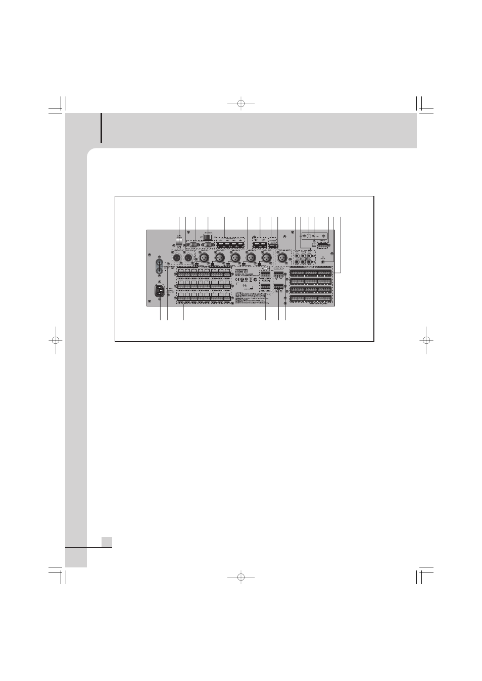
Rear Panel
Rear Panel
1. POWER INPUT (AC INLET)
The terminal connects a power cable.
Before connecting a power cable to it, you must confirm the power voltage conforms the device voltage
exactly.
2. DC POWER INPUT AND BATTERY CHARGE TERMINAL
It is the terminal that supplies emergency power to the system and charges a battery, to which DC 24V
battery is connected.
1) Priority is given to AC power when AC and DC power are input simultaneously. And the system is
operated by DC power when AC power is cut off.
2) In case that driven by the emergency power, when DC electric potential lowers up to 20V, “DC” display
lights on the system operational indicator, and when DC electric potential lowers below 19.2V, it is
converted into Standby State automatically to protect the battery.
※ If it is converted into Standby State automatically causing by battery discharge, it can operate the
system with the emergency power after having charged it to a certain stable quantity (more than 20V).
3) When utilizing the battery charge function simultaneously, turn on the charge function switch located on
the rear panel, but if not, turn off it.
※ You must confirm the voltage and polarities of a battery before connecting it.
3. SPEAKER OUTPUT TERMINALS
Connecting terminals per each of the all channels, which can be connected by normal broadcast (2 line
type) and emergency broadcast (3 line type). One terminal has 3 pins which are named with HOT, COM,
and EM from left.
1) Speaker output terminal operation
7 8
9
11
10
5
4
6
3
2
1
12
13
14 15
16
18
17
20
19
21 22
PAC5000_E 2008.7.1 5:59 PM 페이지 13