H. tank control, I. circulator sizing, Part 7 - fluid quality – HTP PHE199-119S User Manual
Page 22: A. solar loop fluid quality, Solar heat exchanger pressure drop
22
LP- 204 REV. 3.25.14
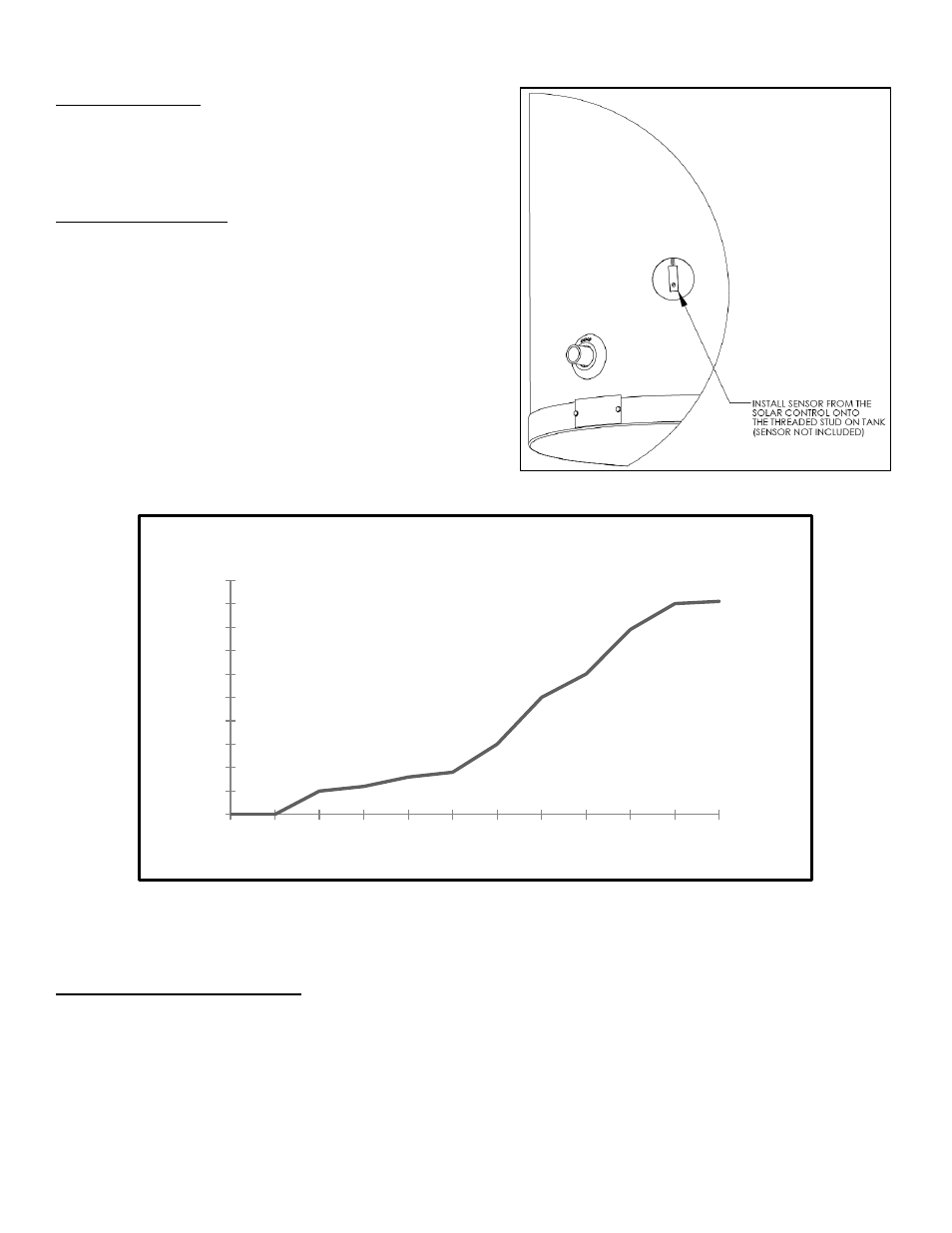
H. TANK CONTROL
Install the solar sensor onto the threaded stud provided in the front of
the water heater (sensor not included). Additional equipment may be
needed in order to wire the control to the existing system. Controls also
have the ability to monitor and display solar collector temperature and
upper and lower tank temperatures. See Figure 10 for installation detail.
I. CIRCULATOR SIZING
The circulator pump must be sized for the related piping and pressure
drop of the heat exchanger, and for situations specific to your solar
system. The following graph represents the pressure drop of the solar
heat exchanger. Consult the solar panel manufacturer for flow
requirements to assist in pump selection.
Figure 10
– Flow Chart – LP-200-L
PART 7 - FLUID QUALITY
A. SOLAR LOOP FLUID QUALITY
Fluid in direct flow through the solar collectors must first meet potable water requirements; any fluid circulated through the collectors
should be non-corrosive to copper. In addition, water quality must meet the following requirements listed below.
Hardness: Less than 7 grains
Chloride levels: Less than 100 ppm
pH levels: 6-8
TDS: Less than 2000 ppm
Sodium: Less than 20 mGL
0
1
2
3
4
5
6
7
8
9
10
1
2
3
4
5
6
7
8
9
10
11
12
Fee
t
o
f fr
ic
tion
Flow in Gallons per Minute
Solar Heat Exchanger Pressure Drop
Figure 9