B. general piping detail, C. solar heat exchanger piping – HTP PHE199-119S User Manual
Page 17
17
LP- 204 REV. 3.25.14
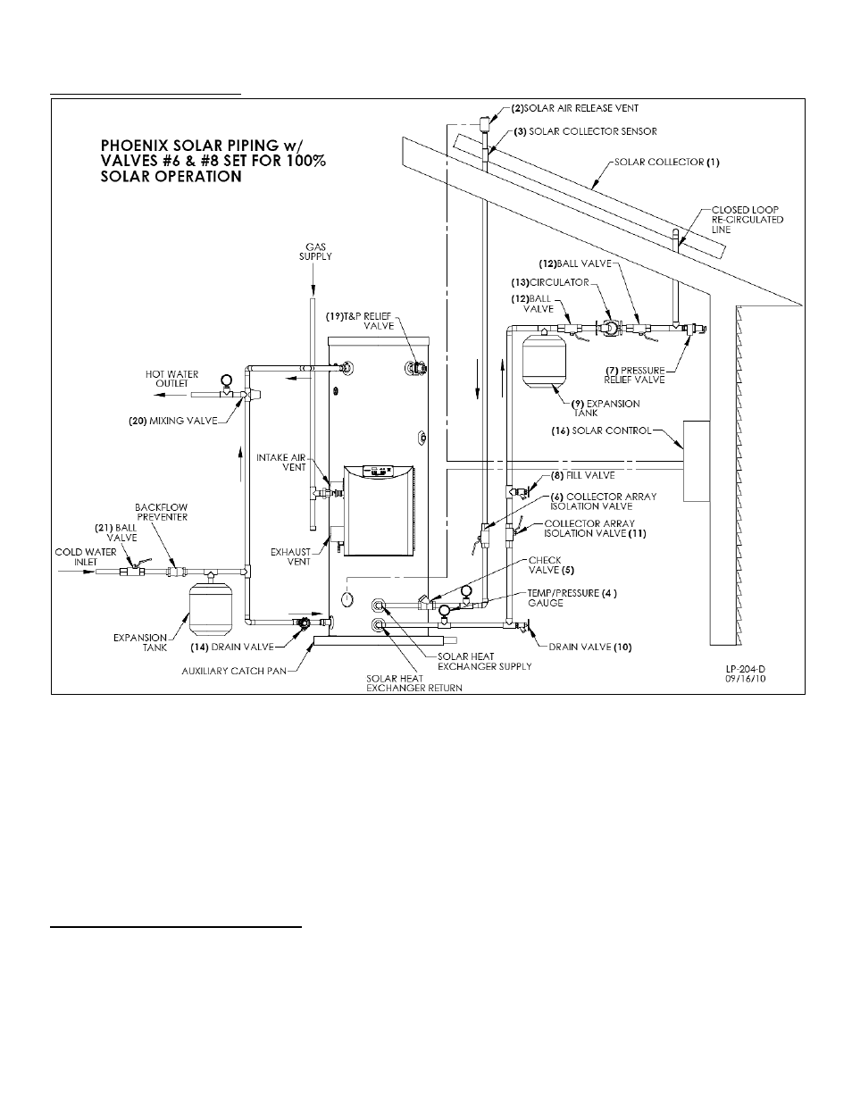
B. GENERAL PIPING DETAIL
Figure 6
– This drawing is meant to demonstrate solar system piping only.
FIGURE NOTES:
1. This drawing is meant to show system piping concept only. The installer is responsible for all equipment and detailing by local codes.
2. Antifreeze, non-potable HTF shall be used for the solar heat exchanger circuit only. Never introduce antifreeze solution to any
connection other than the solar loop.
3. If there is a check valve on the cold water feed line, a thermal expansion tank suitable for potable water must be sized and installed
within this piping system between the check valve and cold water inlet of the solar water heater.
4. An ASSE 1017 mixing valve is required per SRCC OG-300.
5. A minimum of 12 diameters of straight pipe must be installed upstream of all circulators.
6. Make sure tank is fully purged of air before power is turned on to the backup heat source.
7. Circulators shown in the above hydronic piping should have an integral flow check or alternately use a stock pump with an external
spring type check valve. (Due to extreme temperatures, circulators with integral flow checks are not to be used in solar
systems. If circulator comes equipped with an integral flow check, remove it.)
C. SOLAR HEAT EXCHANGER PIPING
Set up the primary balance of the system components following the piping detail in Figure 6.
Run ½” type M or larger copper pipes, or flex line sets, to and from the collector following the direction of supports, penetrations, and
other relative items.
Only copper, cast iron, or brass are to be allowed in the collector piping loop due to transient operating temperatures that may reach as
high as 300
o
F. PEX, PVC, CPVC, and other polymers are expressly prohibited in the piping network of closed loop systems.