F. solar piping with air handler – HTP PHE199-119S User Manual
Page 20
20
LP- 204 REV. 3.25.14
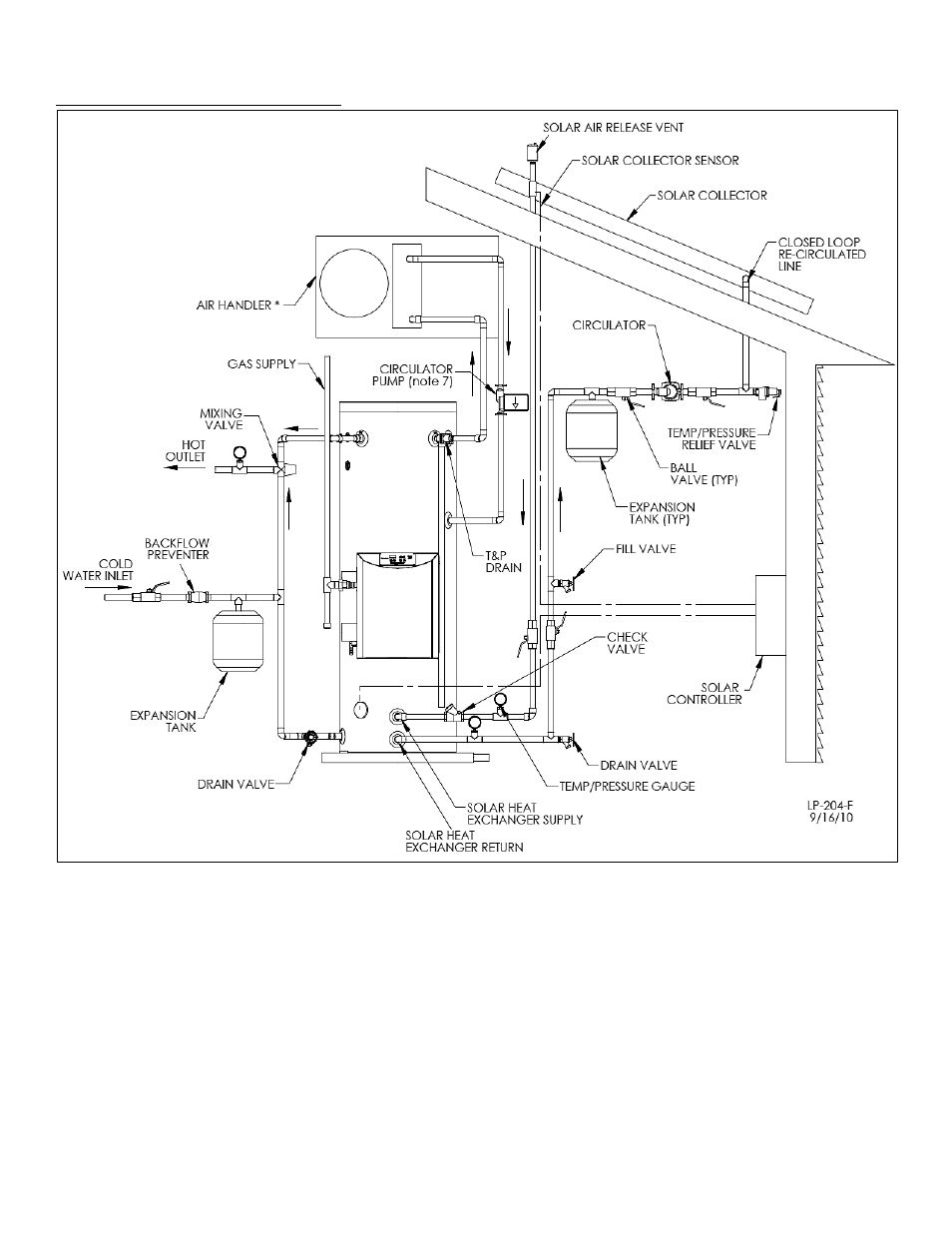
F. SOLAR PIPING WITH AIR HANDLER
Figure 7 - This drawing is meant to demonstrate system piping concept only.
FIGURE NOTES:
1. This drawing is meant to show system piping concept only. The installer is responsible for all equipment and detailing by local codes.
2. Antifreeze, non-potable HTF shall be used for the solar heat exchanger circuit only. Never introduce antifreeze solution to any
connection other than the solar loop.
3. If there is a check valve on the cold water feed line, a thermal expansion tank suitable for potable water must be sized and installed
within this piping system between the check valve and cold water inlet of the solar water heater.
4. An ASSE 1017 mixing valve is required per SRCC OG-300.
5. A minimum of 12 diameters of straight pipe must be installed upstream of all circulators.
6. Make sure tank is fully purged of air before power is turned on to the backup heat source.
7. Circulators shown in the above hydronic piping should have an integral flow check or alternately use a stock pump with an external
spring type check valve. (Due to extreme temperatures, circulators with integral flow checks are not to be used in solar
systems. If circulator comes equipped with an integral flow check, remove it.)