G. solar piping with central heating – HTP PHE199-119S User Manual
Page 21
21
LP- 204 REV. 3.25.14
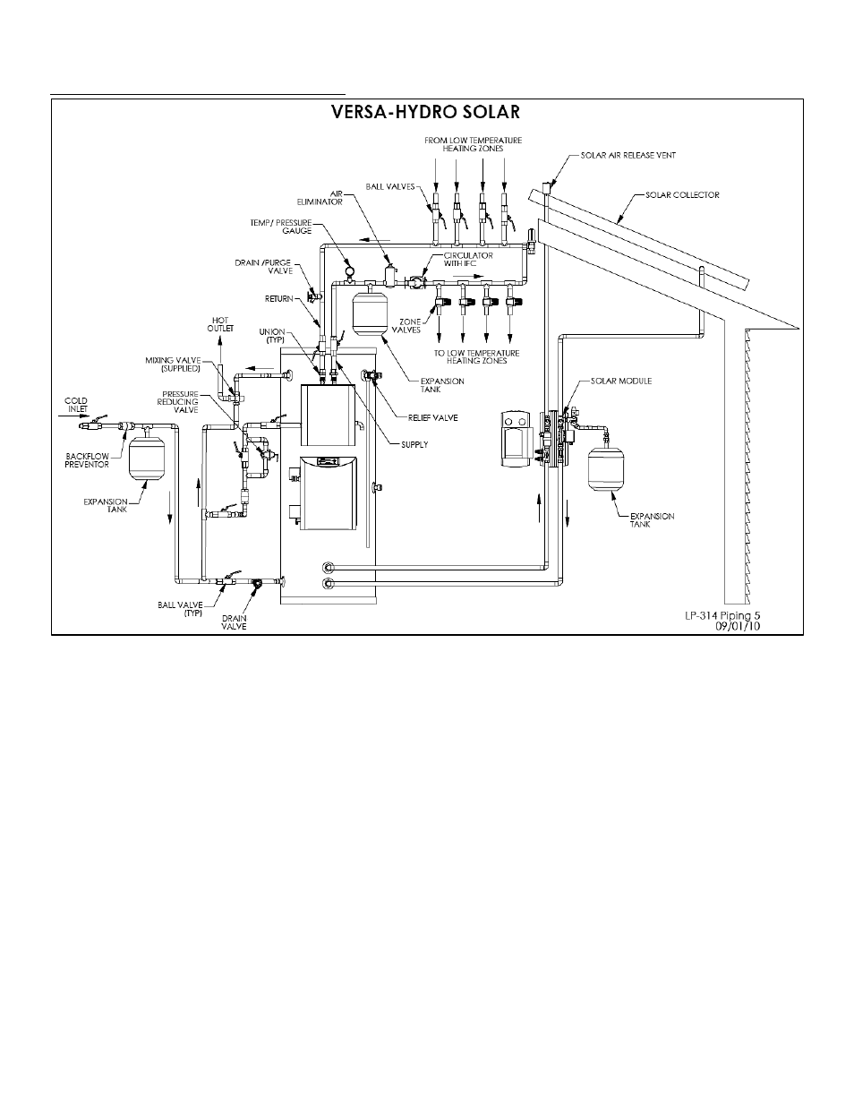
G. SOLAR PIPING WITH CENTRAL HEATING
Figure 8
FIGURE NOTES:
1. Minimum pipe size should match connection size on appliance. If you require greater flow, upsize pipe accordingly.
2. A thermal expansion tank suitable for potable water must be sized and installed within the piping system between the
check valve and cold water inlet of the appliance.
3. Gas line must be rated to the maximum capacity of the unit. Unit must have 10 feet of pipe after gas regulator.
4. All circulators shall have an integral flow check.
5. An ASSE 1017 mixing valve is required per SRCC OG-300.
NOTES FOR AIR HANDLER APPLICATION
1. Massachusetts state plumbing code requires a distance no greater than 50 feet from the water heater to the fan coil in the air
handler.
2. Massachusetts state plumbing code requires an electronically times circulator pump to activate every six hours for 60 seconds. This
circulator must be bronze or stainless.
3. All water piping must be insulated.
4. A vacuum relief valve must be installed per Massachusetts CMR248.
NOTE: This drawing is meant to show system piping concept only. The installer is responsible for all equipment and detailing
required by local codes.