HTP CG300N65 User Manual
Page 8
8
LP-436 REV. 3.21.14
The water heater must be located close to a suitable free-
flowing floor drain. Where a floor drain is not adjacent to the
water heater, a suitable drain pan must be installed under the
water heater. See Figure 10 for proper installation. The drain
pan should be at least 4” (10.2 cm) larger than the diameter of
the water heater, and at least 1” (2.5 cm) deep, providing
access to the drain valve. This pan must not restrict the flow of
ventilation and combustion air. This pan must be piped to a
suitable drain to prevent damage to property in the event of a
water leak from the piping, the temperature and pressure relief
valve, or the water heater. Failure to follow this warning could
result in property damage, severe personal injury, or death.
All water heaters will leak. The manufacturer, based on
national building codes, has given the necessary
instructions to prevent damage to the building. Under no
circumstances is the manufacturer to be held liable for any
water damage in connection with this water heater. See
Figure 10 for proper installation.
This water heater IS NOT design certified for installation in a
manufactured (mobile) home or for installation outdoors.
Failure to follow this warning could result in property damage,
severe personal injury, or death.
This water heater is approved for installation on either a
combustible or non-combustible floor. However, should this water
heater be installed directly on carpeting, the carpeting must be
protected by a wood or metal panel beneath the water heater.
This panel
must extend at least 3” (7.6 cm) beyond the width and
depth of the water heater. Should the water heater be installed in
an alcove or closet, the entire floor area must be covered by the
panel. The panel must be strong enough to carry the weight of the
water heater when it is full of water (CG-73 = 1040 lbs., CG-65 =
1010 lbs.)
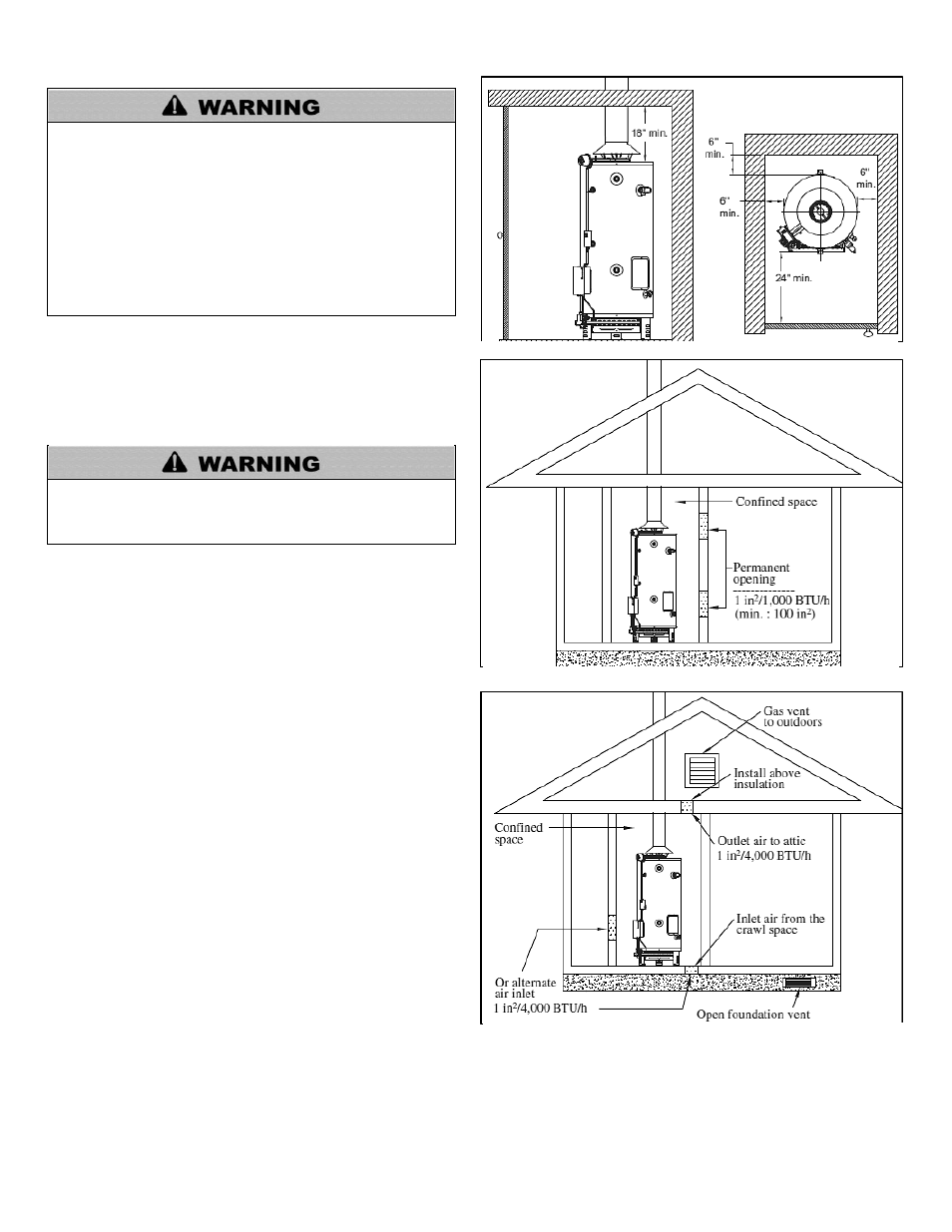
Minimum Clearances
The minimum clearances from combustible materials for this
water heater are: 6” (15.2 cm) from the sides and rear, 24” (61
cm)
from the front, and 18” (45.7 cm) from the top.
Combustion and Ventilation Air Supply
In order for the water heater to operate properly, it must be
supplied with an uninterrupted flow of clean combustion and
ventilation air. The area around the water heater must always be
kept clear so that the flow of combustion and ventilation air is not
blocked. An inadequate supply of air to the water heater will
produce a bright yellow burner flame, causing sooting in the
combustion chamber, on the burners, and in the flue tubes. This
can result in damage to the water heater and serious bodily injury
if not corrected.
Combustion and ventilation air requirements are determined by
the water heater location. Water heaters are installed in either
open (unconfined) spaces or smaller (confined) spaces, such as
closets or small rooms.
Requirements for Unconfined Spaces
An unconfined space is an area with at least 50 cubic feet for each 1,000 BTU/H of the total input rating for all gas-fired appliances
installed in that space. Water heaters installed in unconfined spaces do not usually require outdoor air to function properly. However, in
buildings with tight construction (heavy insulation, vapor barriers, weather stripping, etc.), and particularly in modern buildings,
Figure 1
– Minimum Clearances
Figure 2
– All Air from Inside the Building
Figure 3
– Communicating Directly with the Outdoors