Part 2, Installation instructions – HTP CG300N65 User Manual
Page 7
7
LP-436 REV. 3.21.14
PART 2 – INSTALLATION INSTRUCTIONS
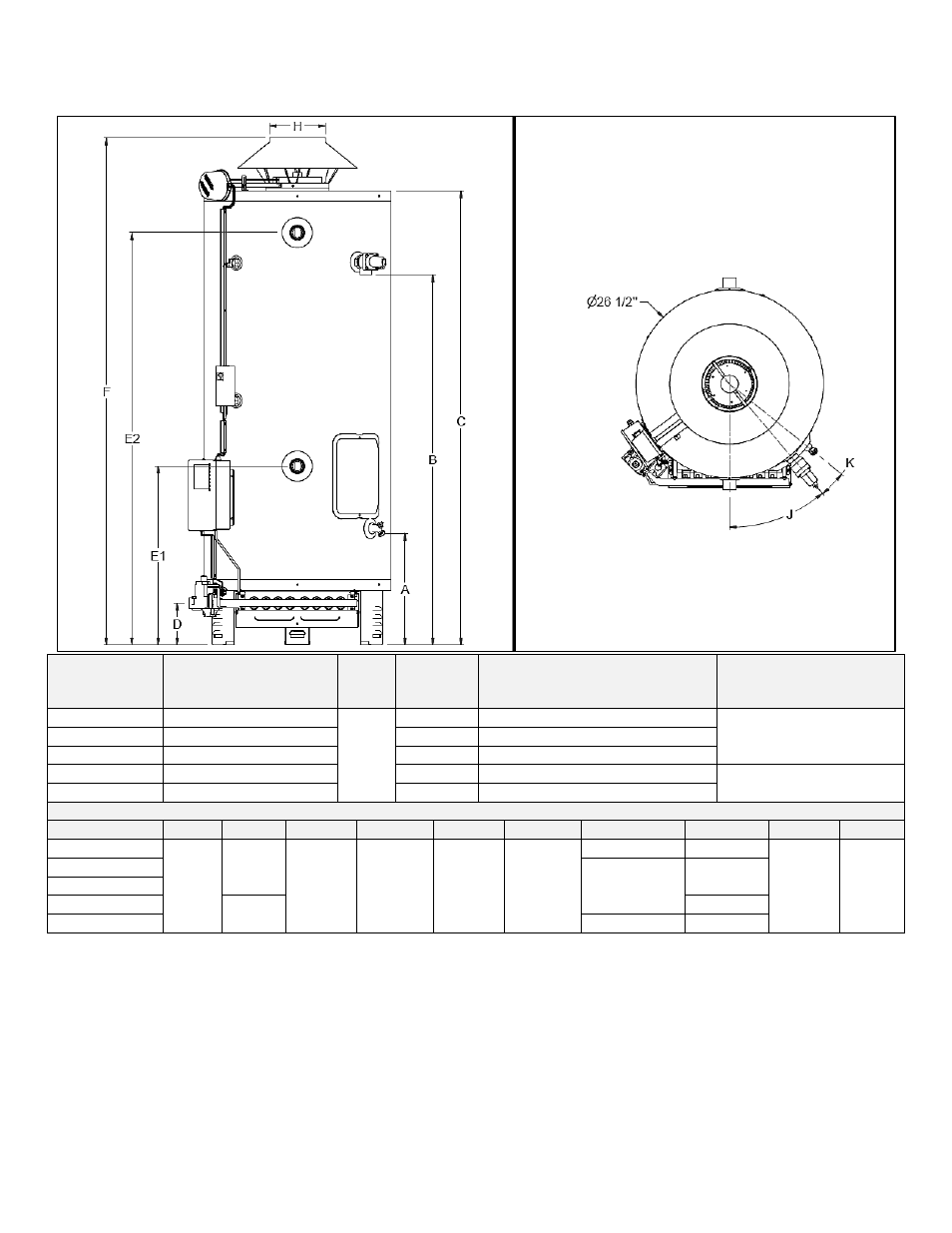
Specifications and Dimensions
MODEL
STORAGE
CAPACITY
GALLONS (LITERS)
FUEL
TYPE
INPUT
(BTU)
RECOVERY 90
o
F / 50
o
C
GALLONS (LITERS) PER
HOUR
SHIPPING WEIGHT
LBS. (EST.)
CG125N73
72 (272)
N
125,000
135 (511)
429
CG150N73
70 (265)
150,000
162 (613)
CG199N73(X)
68 (257)
199,900
215 (814)
CG250N65
60 (227)
250,000
269 (1018)
465
CG300N65
55 (208)
300,000
323 (1223)
MODEL DIMENSIONS IN INCHES
MODEL
A
B
C
D
E1
E2
F
H
J
K
CG125N73
15 ¾
52 ½
64 1/8
5 7/8
25 ¼
58 ¼
69 ¼
5
40.3
o
51.2
o
CG150N73
70 7/8
6
CG199N73(X)
CG250N65
52 1/8
7
CG300N65
71 5/8
8
Table 1
– Specifications and Dimensions – NOTE: All Water Heaters Shipped to Operate on Natural Gas – A suffix of “X”
denotes model set for Low NOx operation
Location
This water heater should be located in a clean, dry location, as close as possible to the chimney and to the main use of hot water. This
location must not be subject to freezing temperatures. Make sure the cold water piping is not located directly above the main gas valve
or any other electrical control. This will prevent water and condensation from dripping on the main gas valve during installation and
operation.
The water heater should be positioned so there is easy access to the main gas valve, flue damper, junction box, temperature and
pressure relief valve, and drain valve. Space must be provided at the front of the water heater so that the burner tray assembly can
slide out for service.