HTP CG300N65 User Manual
Page 10
10
LP-436 REV. 3.21.14
Corrosive Atmospheres
If this water heater is to be installed in a beauty shop, barber shop, photo processing lab, dry cleaning establishment, a building with an
indoor pool, or near a chemical storage area, it is imperative that the combustion and ventilation air be drawn from outside these areas.
These particular environments contain products such as aerosol sprays, detergents, bleaches, cleaning solvents, refrigerants, and
other volatile compounds that, in addition to being highly flammable, become highly corrosive acid compounds when burned. Exposure
to such compounds can be hazardous and lead to premature product failure. Should the water heater fail due to exposure to such a
corrosive atmosphere, the warranty is void.
Venting
When installing the venting system, make sure to follow all local codes, or, in the absence of local codes, National Fuel Gas Code,
ANSI Z223.1/NFPA 54 in the United States, or CAN/CSA B149.1, National Gas and Propane Installation Code in Canada. Never
operate the water heater unless it is properly ventilated to the outdoors and has adequate air supply for proper operation. Failure to
properly install the venting system could result in property damage, personal injury, or death.
High heat sources (sources generating heat 100
o
F / 37
o
C or greater, such as stove pipes, space heaters, etc.) may damage plastic
components of the water heater as well as plastic vent pipe materials. Such damages ARE NOT covered by warranty. It is
recommended to keep a minimum clearance of 8” from high heat sources. Observe heat source manufacturer instructions, as well as
local, state, provincial, and national codes, laws, regulations and ordinances when installing this water heater and related components
near high heat sources.
Automatic Flue Damper/Drafthood Assembly
The flue damper/drafthood assembly has been shipped from the factory in a separate box attached to this water heater. Before
installing the flue damper/drafthood assembly, verify that it is the correct model for this water heater (the CG125N73
uses a 5” flue
damper, all other
73 gallon models use a 6” flue damper; CG250N65 uses a 7” flue damper, all other 65 gallon models use an 8” flue
damper). If the wrong assembly has been shipped or is missing completely, immediately contact the dealer where the water heater was
purchased. Never operate this water heater without the manufacturer’s flue damper/drafthood assembly installed.
DO NOT modify the flue damper / drafthood assembly in any way. DO NOT turn on the electrical power to the water heater until the flue
damper / drafthood assembly is installed. Failure to follow these instructions can result in property damage, personal injury, or death.
When installing the water
heater, make sure the
location allows clear
viewing of the flue
damper. When the damper
is in the open position, the
paddle is perpendicular to
the water heater. The flue
damper must be in an
open position when the
water heater’s burners are
operating.
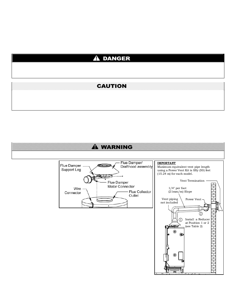
To install the flue damper/drafthood assembly, use the following instructions and secure
all pieces with the provided sheet metal screws. See Figure 6.
1. Remove the flue damper/drafthood assembly from its packaging.
2. Center the assembly over the flue collector outlet.
3. Rotate the assembly so that the wire connector on the water heater can plug into the
flue damper motor connector.
4. Use the wire connector to secure the assembly to the flue connector.
5. Install the flue damper support leg on the assembly.
6. Secure the assembly to the top of the water heater.
7. Plug the wire connector on the water heater into the flue damper motor connector.
Venting System
The venting system must be attached to the drafthood to connect the water heater to the
gas vent or chimney. The vent pipe connecting the water heater must be of the same
size as the drafthood outlet. It is highly recommended to install this water heater on a
Figure 6
– Flue Damper/Drafthood Assembly
Figure 7
– Power Vent Kit Installation