HTP CG300N65 User Manual
Page 12
12
LP-436 REV. 3.21.14
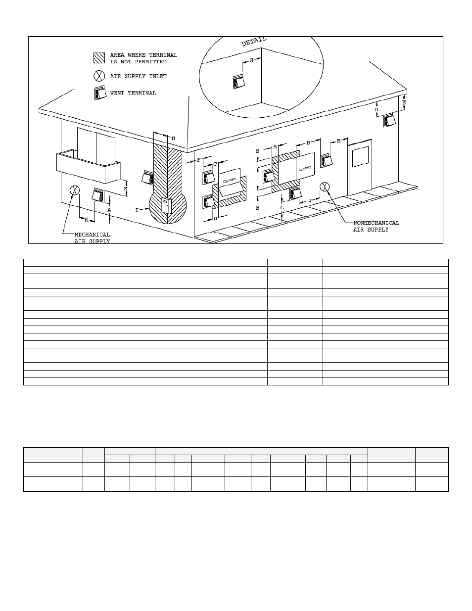
Figure 8
– Vent Installation Detail
WHEN USING A POWER VENT KIT, THE VENT TERMINATION MUST HAVE:
US Installations
1
Canadian Installations
2
A) Clearance above grade, veranda, porch, deck, or balcony
12”
30 cm
B) Clearance to window or door that may be opened
3’
1.2 m below or to the side of opening; 30
cm above opening
C) Clearance to permanently closed window
*
*
D) Vertical Clearance to ventilated soffit located above the terminal within a horizontal
distance of 2’ from the center line of the terminal
*
*
E) Clearance to unventilated soffit
*
*
F) Clearance to outside corner
*
*
G) Clearance to inside corner
*
*
H) Clearance to each side of center line extended above meter/regulator assembly
3’
*
I) Clearance to service regulator vent outlet
3’
*
J) Clearance to non-mechanical air supply inlet to building or the combustion air inlet
to any other appliance
3’
1.2 m below or to the side of opening; 30
cm above opening
K) Clearance to a mechanical air supply inlet
6’
91 cm above if within 3 m horizontally
L) Clearance above paved sidewalk or paved driveway located on public property
7’
†
2.13 m
M) Clearance under veranda, porch, deck, or balcony
12”
‡
*
Table 2
– Power Vent Kit Installation Requirements
1
In accordance with current ANSI Z223.1/NFPA 54 National Fuel Gas Code.
2
In accordance with the current CAN/CSA B149.1 National Gas and Propane Installation Code.
*
Clearance in accordance with local installation codes and the requirements of the gas supplier.
†
Vent shall not terminate directly above a sidewalk or paved driveway located between two single family dwellings that serves both dwellings.
‡
Permitted only if veranda, porch, deck, or balcony is fully open on a minimum of two sides beneath the floor.
MODEL
KIT#
MOTOR
DIMENSIONS (INCHES)
VENT HOOD
ROUGH-IN
INLET /
OUTLET
Watts
Amps
A
B
C
D
E
F
G
H
I
J
CG125N73
1
95
1.26
7
7/8
7
11
4
7½
(sq)
7
1/8
13
(sq)
8
5/8
7 3/8
11
8
(sq)
4
CG150N73 to
CG300N65
2
224
1.51
9¼
8½ 11½ 6
8½
(dia)
7
7/8
12
(sq)
9½
9½
10
9
(dia)
6
Table 3
–
Power Venter Including Terminal - NOTES:
Max vent length based on total of straight vent pipe plus 11’ for 6” dia. 90
o
elbow, 7’ for a
4” 90
o
elbow, 5’ for a 6” 45
o
elbow, 4’ for a 4” dia. 45
o
elbow, 4’ for a 8” to 6” reducer, and 5’ for a 6” to 4” reducer.