Part 2 - installation, A. wiring requirements – HTP 7350P-629 User Manual
Page 5
5
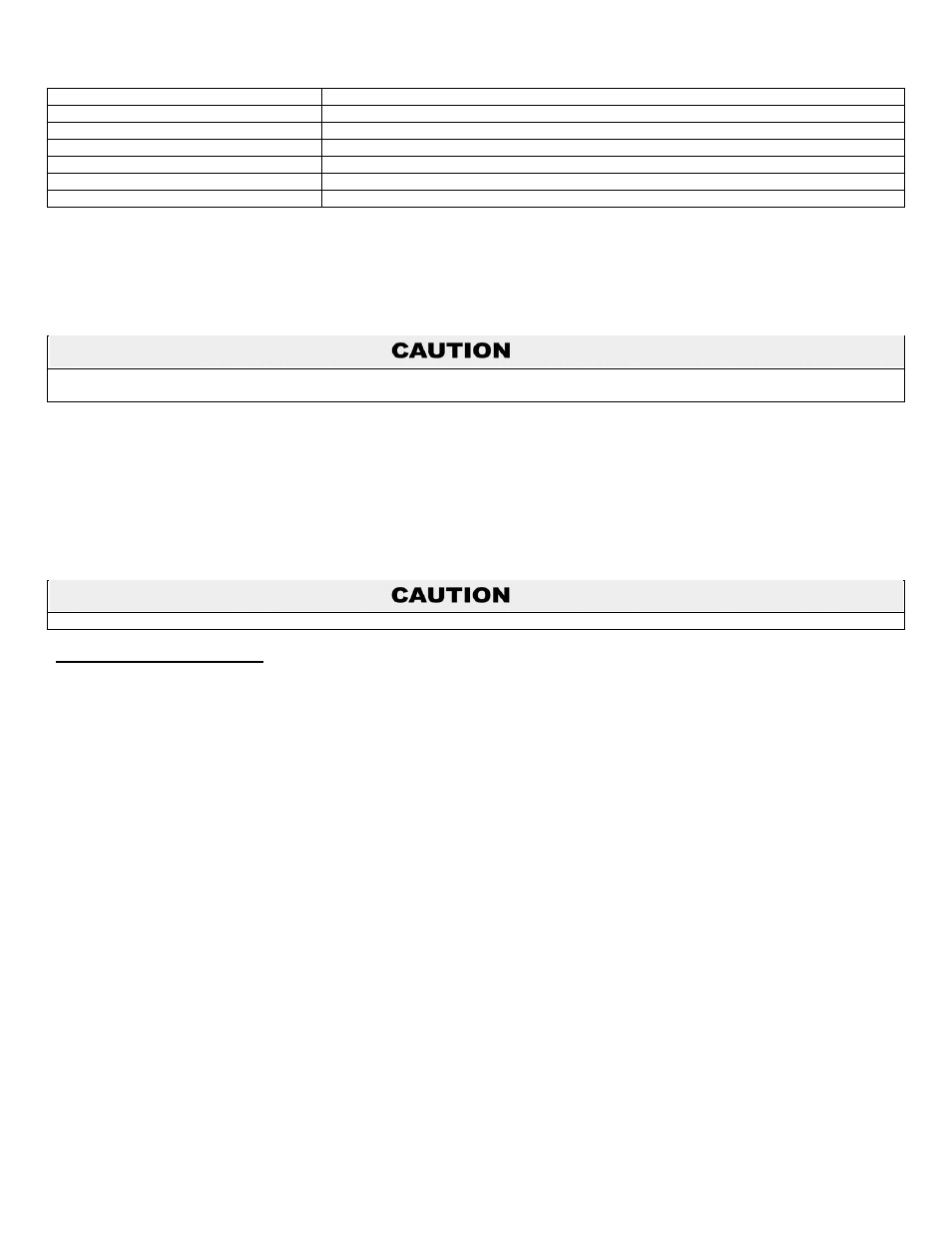
Modbus
A serial, half-duplex transmission protocol developed by AEG Modicon
MSB
Most Significant Byte
RS232
RS232 serial, full-duplex (FDX) transmission of data standard
RS485
RS-485 serial transmission of data standard
RTU
Remote Terminal Unit
PG
Industry Standard liquid-tight wiring entry connector
MB
MODBUS
Table 1
– Acronym definitions
PART 2 - INSTALLATION
The Modbus adapter should be mounted to a solid surface. The adapter has two tabs with four mounting holes designed specifically for
this purpose.
Use the mounting screws provided with the adapter. Damage to Modbus adapter or appliance due to installation with other mounting
screws IS NOT covered by warranty.
When mounting the unit, keep in mind that the top cover must be removed to connect the Modbus communication cable, and that the
appliance communication wire must reach the control inside the appliance.
The Modbus adapter can be mounted on the side of the appliance OR the wall next to the appliance, as long as care is taken to avoid
components behind the mounting surface. The mounting location must be within 3 feet of the appliance controller in order to be plugged
into the controller programming port.
NOTE: It is not recommended to install the Modbus adapter inside the appliance housing. Doing so may affect appliance operation or
damage the Modbus adapter.
Damage to Modbus adapter or appliance due to improper installation IS NOT covered by warranty.
A. WIRING REQUIREMENTS
RS-485 Communication Bus
Maximum length: 1000 feet
Cable specification: 24 AWG / A,B (twisted pair) and GND shielded, with characteristic impedance: 120 ohm
Maximum load: 32 units (32 nodes)
Wires will be passed through the PG connector on the side of the adapter, then connected to the three position connector
marked “X5”
on the circuit board inside the adapter. A label is provided inside the adapter to ensure proper connections of A, B, and GND. Two wires
(MB IN and MB OUT) may be attached to each X5 screw.
See Figure 2 for an example wiring diagram.