F. rate and temperature conversions – HTP 7350P-629 User Manual
Page 17
17
Please note that with Modbus communication connected only to the master appliance, only total cascade information can be seen
through the communications link. Information from the follower boilers is limited to follower appliance rate command, supply
temperature, fault code, and fault status.
If you want to see complete data from each follower, or use the Modbus master to control cascading of multiple appliances, each
appliance will need a Modbus communication board.
Monitoring Only
Any appliance can be equipped with the Modbus communication accessory and then be set up to operate with its own internal controls.
The Modbus master can then poll the Modbus accessory for the read only variables.
F. RATE AND TEMPERATURE CONVERSIONS
Rate
When issuing a rate command, the rate can be communicated as percent modulation or a desired set point temperature depending on
the setting of parameter 16 in the appliance Installer Menu. Proper data format for the modulation percentage is direct conversion to
hexadecimal. This conversion can be accomplished through online number based converters or some scientific calculators.
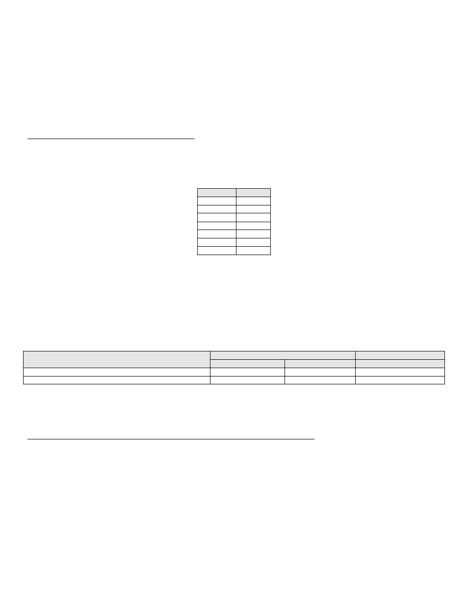
For example:
RATE %
HEX
0
00
20
14
45
2D
60
3C
80
50
95
5F
100
64
Table 18
Temperature Conversions
To send a desired set point, the hexadecimal value must be determined through linear interpolation of programmable parameters on
the BMS setup menu.
BMS temperature set point at low analog input
BMS temperature set point at high analog input
These variables set the temperature values corresponding to the minimum and maximum voltage settings of the 0
– 10 volt signal. The
defaults are as follows:
PARAMETER
DEFAULT VALUES
DEFAULT
Deg C
Deg F
Voltages
BMS temperature set point at low analog input
21
69.8
2
BMS temperature set point at high analog input
82
179.6
10
Table 19
For example: Send a set point of 110
o
F. The formula to use for the interpolation is:
Rate Command =
(Desired set point
– BMS temp at low analog input) (High voltage – low voltage) + Low voltage
(BMS temp at high analog input
– BMS temp at low analog input)
From the default values:
Desired set point = 110
BMS temp at low analog input = 68
BMS temp at high analog input = 158
High voltage = 10
Low voltage = 2
[(110 - 69.8)(10-2)/(179.6 - 69.8)] + 2 = 4.92 volts
(4.92/10) x 100 = 49.2
49 = 31 Hexadecimal
A value of [00] [31] in hexadecimal would be written to holding register 40003 to issue a command for a 110
o
F set point.