Rivers Edge RE627 Oasis User Manual
Page 13
Check for parts online at
www.huntriversedge.com or call 800-450-EDGE (3343) M-F 8-5
13
Operator's Manual
Rivers Edge® One-Man Ladder Stands
14. Thread the non-locking 3/8-16 nut onto the threaded end of
spacer rod all the way to the bottom of threads and slide 3/8” lock
washer on. Insert the threaded end of spacer rod through either
backrest mount tube far enough to be able to insert the opposite
end of spacer rod (end with welded-on washer) into opposite
backrest mount tube. Thread 3/8-16 nut back against mount tube.
Using a 9/16” wrench, tighten nut until mesh backrest becomes
taut. sEE fIGuRE 10. You must now tighten all nut and bolt
assemblies. Be sure not to over tighten or crush tubing when
tightening!
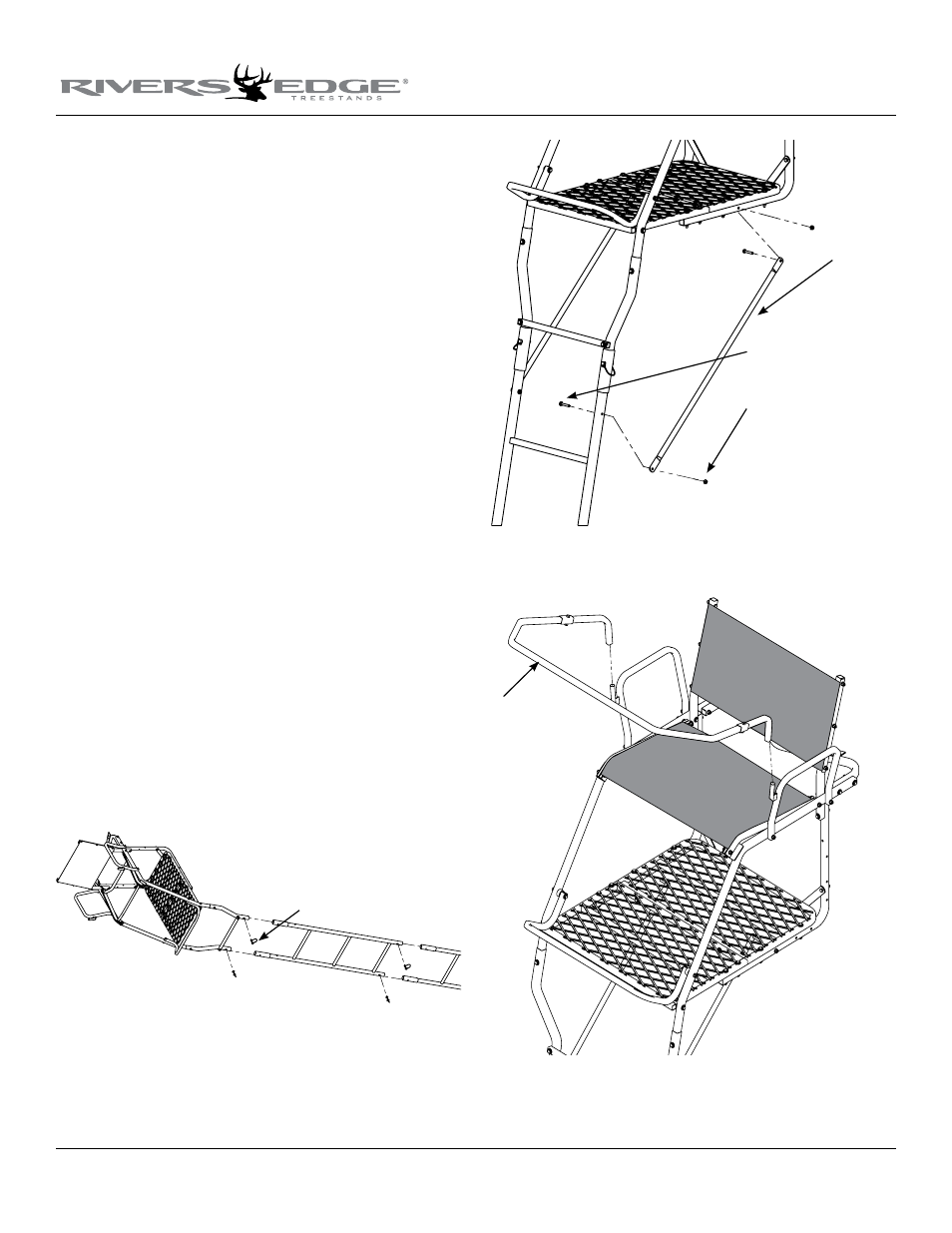
15. Sections are assembled on the ground in the following order; bot-
tom section (410066 3-step ladder); second section (410068 3-step
ladder with stabilizer bar mount); third section (410069 3-step
ladder w/ mounting holes); top section (assembled top platform
section). sEE fINIshED 17’ OAsIs lADDER.
16. With all sections assembled together on ground, secure all sec-
tions together using (6) provided spring lock pins. Handle of
spring lock pin must be put to the outside of ladder side rails.
sEE fIGuRE 11.
17. Attach the (2) support braces (410024) to the inside of platform
support rails and outside of top ladder section w/ mounting holes
using (4) provided 1/4-20 x 1-1/2” bolts and locknuts. sEE fIGuRE
12. Tighten securely. Be sure not to over tighten or crush tub-
ing when tightening!
18. a. Attach the removable shooting rail by setting rail down over
studs provided on armrests. sEE fIGuRE 13. lubrication is rec-
ommended to prevent binding and noise.
b. Attach the (2) provided 9” and (1) provided 47” camo foam pads
to the armrests and shooting rail by wrapping around tubing and
attaching velcro together.
c. Attach foam padded seat bumpers (48102) to bottom side of
front seat spacer assembly. Surface must be clean and at room
temperature to assure proper adhesion.
Figure 11
spring lock pins
Figure 12
Figure 13
support braces
1/4-20 x 1-1/2" bolts
shooting
rail
locknuts