5 test inspection procedure, 6 pc mode – Acer P1166 User Manual
Page 69
Confidential
4-3
P1166 / P1266 / P1266i / P1166P / P1266P
4-5 Test Inspection Procedure
Charge parts
Update
Main
Board
Firmware
Color Wheel
Lamp Module
EDID
Lamp
Driver
Version Update
v
v
v
Color Wheel Index
v
v
Reset lamp hour
v
OSD Reset
v
v
EDID
v
Re-write Lamp
Hour Usage
v
Default Language
Reset
v
v
v
Waveform
Download
v
4-6 PC MODE
Note: Test signal: analog 800 x 600@60Hz (for P1166/ P166P),
analog 1024 x 768@60Hz (for P1266 / P1266i /
P1266P). We take P1266 for example.
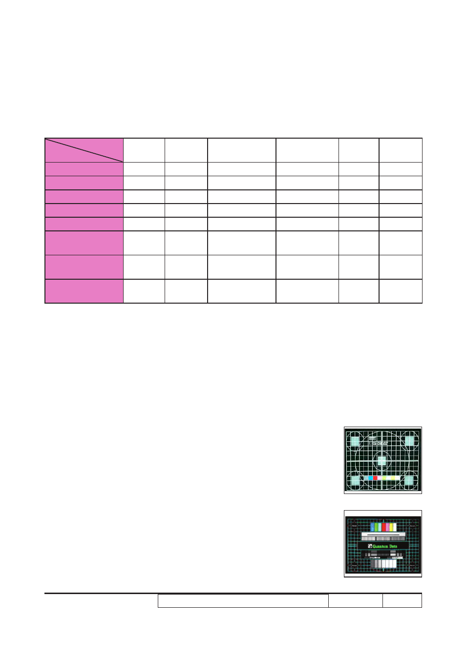
1. Frequency and tracking boundary
Procedure
- Test equipment: video generator.
- Test signal: analog 1024 x 768@60Hz
- Test Pattern: general-1 or master
- Check and see if the image sharpness is well-
performed.
- If not re-adjust by the following steps:
(1) Select "Frequency" function to adjust the
Note: If Color appears abnormal after changing Main Board Module, please do Color Wheel index
adjustment.
General-1
Master